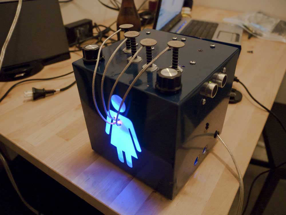
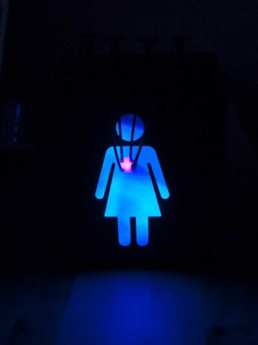
It’s Done! I gave it to my sister last weekend and she really liked it. If you’re just tuning in now, I have posts about the hardware development, waveform crafting, an early demonstration, and the software algorithm. The final version has the following features:
- Four octaves of continuous pitch variation by moving your hand nearer or farther from an ultrasound sensor
- Digital volume control
- Continuous waveform variation–can generate a pure sine tone like a classic theremin, or one with overtones, which sounds like an 80’s synth organ.
- Spectral glide–similar to a Wah pedal or the instrument used in Peter Frampton’s ‘Do You Feel Like I Do’
- Decay/Sustain–envelope shaping to play notes
- Distortion–sounds like the guitar effect.
Listen to the Tone of the Future:
[audio:https://www.maxpierson.me/wp-content/uploads/2009/06/Theremin-Synth-Rev1.mp3]- 0:00-0:00 Pure tone, no effects
- 0:45 Waveform selection– no overtones
- 1:05 Decay effects
- 1:37 Wah
- 2:45 Distortion
And here is a video with me demonstrating the operation (and also explaining several key features completely incorrectly):
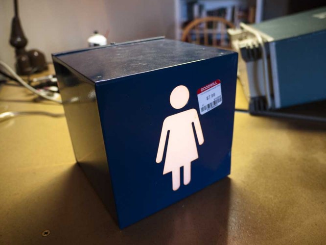
The Enclosure and Parts Sourcing: I think this is a sign for stores to put out if their restrooms are somewhat difficult to locate. It was $8, which is kind of a lot for broken down Goodwill electronics, but as soon as I saw it I had to have it. I also purchased an old clock radio for $2 for the power supply and speaker, and some kind of broken weather clock thingy for the blue LEDs for $0.50.
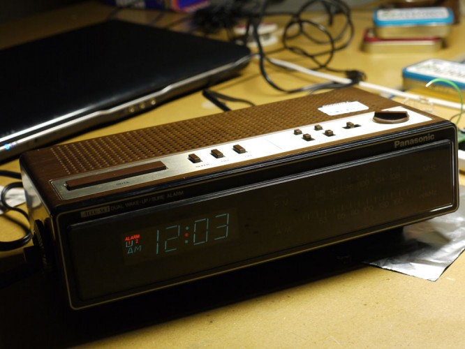
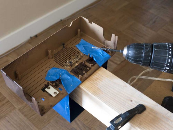
A lot of the parts were salvage from obsolete electronics that I’ve kept for that reason. Total cost for the project was about $100, but a lot of that was ‘research’, AKA ‘buying things that I think will solve my problem, but don’t.’ I think the total cost if I just bought everything I needed the first time would be around $60, not including the enclosure. The Arduino Pro ($23) and Parallax Ping ($30) were the big-ticket items.
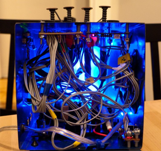
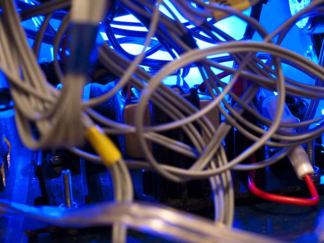
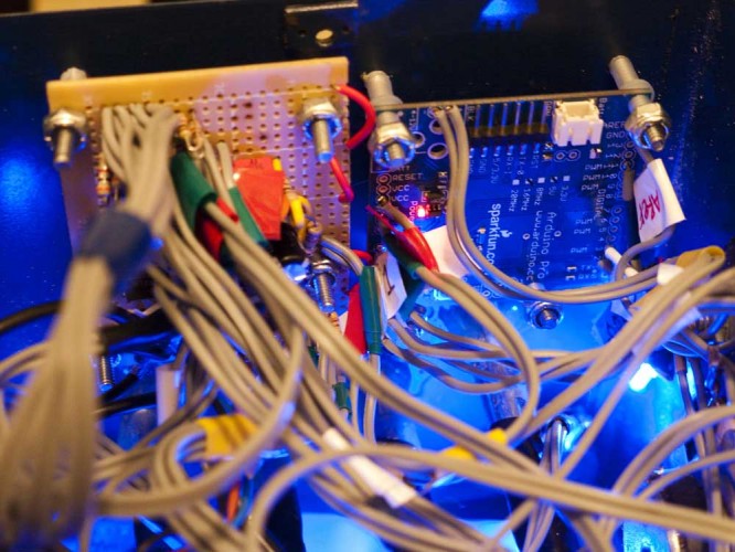
This is an Unholy Mess. Let’s just get that out of the way. I designed/built it part-by-part, on breadboard, then added each component onto the protoboard as I finished it, then crammed everything into the enclosure at the very end. So the schematics I’m showing you were done after the fact, ymmv, the impermanence of memory, etc. But it works, which is more than I can say for my fucking oscilloscope.
 Power Supply and Case Lighting: I just cut out the part of the radio chassis that had the transformer, and used that to mout it on the enclosure. It’s a center-tap, 12:1 transformer, pretty standard. I don’t like using line voltage in my projects, but I added a fuse and made sure the case was grounded, so it’s reasonably safe, I think. The diodes, fuse holder, and smoothing capacitor were also salvage, from something else I had laying around. The blue LEDs came from some kind of broken weather clock thingy that I bought at Surplus Gizmos for $0.50. Here’s the schematic:
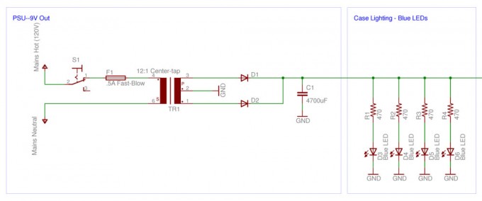
The 9V powers the Arduino, which can take from 5-12V, and the sensor LEDs and ICs (not shown above). Then I took the 5V output provided by the onboard voltage regulator on the Arduino and used it to power the things that had to have 5V, such as the Ping and photoresistor sensors.
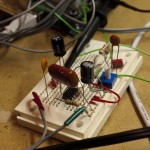
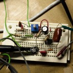
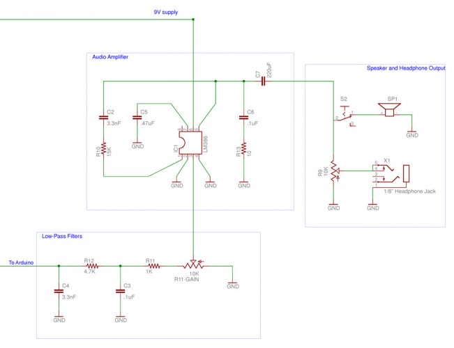
Audio Output: The audio signal is generated from a PWM pin, as outlined here. From there it passes through two low-pass filters that get rid of the noise from the pin banging on and off. These can be omitted as the speaker will mostly filter anything that high out, but it sounds better with them. Here’s some pictures of the audio circuit while it was still on breadboard:
Next it’s amplified by the ubiquitous and much-maligned LM386 audio amplifier. I’m using the example circuit from the datasheet with the 6dB bass boost. On the advice of the nice people from DIY audio forums, I increased the zobel capacitor from .05uF to .1uF, which got rid of a nasty high pitched tone when I connected the speaker.
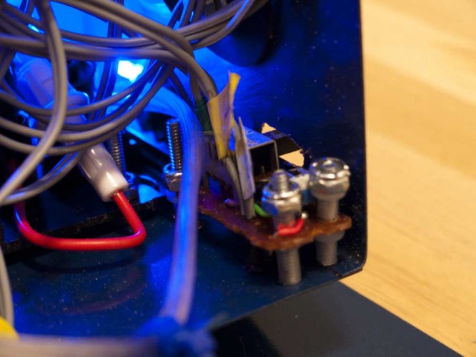
Finally, it passes to the speaker and headphone jack, mounted in the bottom corner of the case:
There’s a switch that allows you to disconnect the speaker (again from the clock radio, which gave so much to this project), and a headphone jack I pulled out of my old CD player, with a 10K pot sitting in front of it to control the output level to the headphones/external amplifier. From the sample you can hear that the volume decreases significantly in the lower frequency range, because the cheap 4″ speaker that I had starts to drop out at around 500Hz. But when I connected it up to my Macintosh 1700 amplifier, it’s a whole different animal :] Here’s the schematic for that section:
 The Sensors: As I covered in a prior post, these are wall anchor hardware with a photocell mounted inside. I discovered that if I moved an LED nearer or farther from the sensor it gave a very linear, stable response.
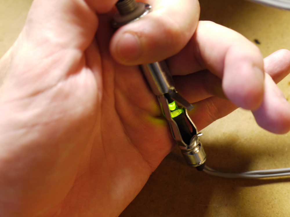
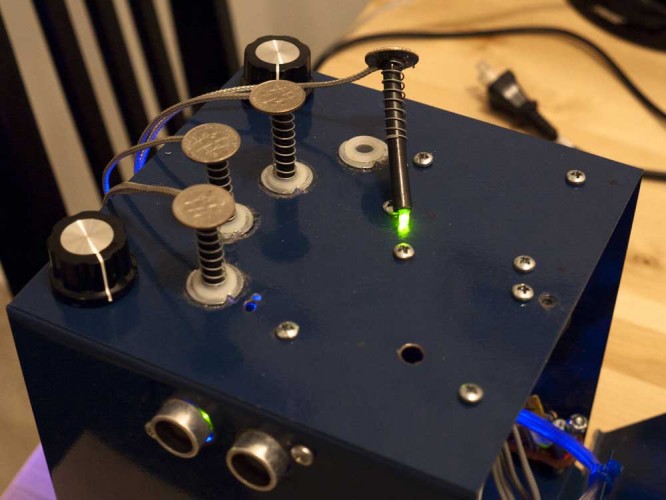 I really like the way the sensors came out aesthetically– I used coaxial cable to do the LED runs, and it has a nice steampunk organ-stop look. Also, with enough fussing I was able to get a very smooth, precise action out of the spring movement. Here’s the schematic:
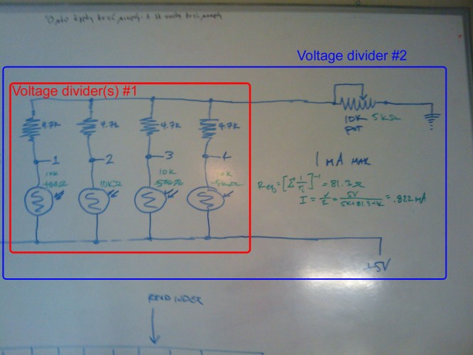
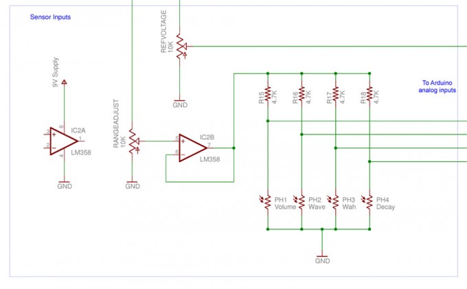 There’s one other trick I should talk about here, which is the use of the LM358 op-amp to provide the supply voltage for the sensors. Originally, my schematic looked like this:
Simple, right? You have the four photoresistors acting as a voltage divider with their respective 4.7Kohm resistors, so as they change in resistance it varies the voltage that the analog input on the Arduino sees. Then, you have a pot feeding all of them, which you can adjust to get the right range selection. The problem was that as I would vary one sensor, it would affect all the others. After a lot of thinking, here’s why: each photoresistor is a voltage divider (#1), but there is also a composite voltage divider made up of the equivalent resistance of all four sensors, and the 10Kohm pot, which would cause the supply voltage to vary feeding into #1. Using an op-amp as a unity-gain buffer amplifier solved this problem. A heartfelt shout out to Ran Talbott on the Arduino forums who suggested the buffer amp.
Also: I also ran an LED from PWM pin 11 on the arduino to just behind the center of the torso, where the sensor LED wires enter the enclosure. I set the value to increment every time the software runs through the main loop, so the heart pulses slower or faster depending on processor load.
The complete schematic is available as a pdf and an Eagle sch file. As I mentioned, the schematic was done from memory, after the fact, so I would breadboard it before you build a custom pcb. If you do design a custom circuit board for it, or improve the hardware, drop me a line, I’d love to hear about it.
The Software: I’ve gone into some detail about the algorithm used in a prior post, so I’ll just cover how the effects are generated. To quickly review, the audio output is generated via pulse width modulation on pin 3. Every time the main loop runs, it reads from the sensors, and transforms the sampled waveform array(s) depending on their input. Pitch control is done by controlling how quickly the timer steps through that array. So we have our sampled arrays:
[cc]
char sine[] = {0,49,90,117,127,117,90,49,0,-49,-90,-117,-127,-117,-90,-49,0,49,90,117,127,117,90,49,0,-49,-90,-117,-127,-117,-90,-49};
//a simple sine wave with 32 samples
char overtones[] = {0,107,118,127,118,92,52,-8,17,46,-6,-36,-56,-67,-70,-80,0,80,70,67,56,36,6,-46,-17,8,-52,-92,-118,-127,-118,-107};
//the same wave with the overtones (and undertone) baked in
[/cc]
And the transformations:
[cc]
  /******************************* Apply volume and effects **********************************/
  if (abs(periodold - period) > 25) {
    decay = 255;
    }
  else {
    decay = ((decay * analog4) / 255);
    }
  //if a new tone is produced, reset decay to full, otherwise increment it downward.
  analog3buffer = float(analog3) / 200;
  //convert sensor 3 to a floating point number in the range of pi/16 to pi/4

  for (byte i = 0; i < SAMPLESIZE ; i++) {
    playbufferelement = (analog2*sine[i] + (255-analog2)*overtones[i]) / 255;
    /* waveform selection-- as analog2 ranges from 0-255 it changes the tone from
    *  a pure sine wave to a more complex wavetype. */

    playbufferelement = playbufferelement*cos(analog3buffer*i);
    /* Wah effect-- creates a variable comb filter.  Note that as cos(0) = 1, when the input
    *  from the sensor is 0, the waveform is unchanged */

    playbufferelement = playbufferelement * analog1 * decay / 65025;
    //volume and decay.

    playbuffer[i] = playbufferelement + 128;
    //bias the values back to 0-255 for PWM output.
  }
[/cc]
This is a conceptually dense section of code, so let me see if I can unpack it. There’s a for() loop that fills up the playbuffer array, which is asynchronously read from by the audio output routine. I managed to keep expensive floating point math to an absolute minimum by multiplying by a byte value, then dividing by 255. In particular,
Waveform Selection: is faded proportionally from the pure tone in the sine[] array to the fundamental+overtones in the overtones[] array. This is done by multiplying the value given in each array by analog2 (0 < analog2 < 255), or 255-analog2, then adding them together and dividing by 255 to scale it back to its original range.
“Wah” is done by multiplying the incoming (sinewave) values by a cosine function, with the frequency of the cosine function set by the analog3 input. This is my one concession on the floating point math thing, and it’s cost in terms of processor speed is considerable. The end effect is to create a variable comb filter. I think. I programmed by ear after my oscilloscope went tits up, so I don’t know with a certainty why it sounds the way it does.
Volume: is done by simply multiplying the value by analog1, which ranges from 0 to 255, and then dividing by 255. So we get a percentage of the 0-255 range.
Decay is similar to volume, but the decay variable is decremented every time the main loop runs with the same frequency. Since it’s multiplied by the new decay value and then divided by 255, it is a logarithmic rather than linear decay–which is why it sounds so natural. The volume and decay calculations are done together and then divided by 255*255 = 65025 to reduce the number of calculations.
Finally, playbufferelement, which at this point ranges over -128 to 127 is increased by 128 to scale it to 0-255 for PWM output.
The software may be downloaded here.
A Final Note: this was a skunkworks project. I pulled an all-nighter on the day before I went to Chicago, to finish the hardware, and the software was finished in Chicago. So there are a lot of hard-coded values and other hacks that reflect the particular parameters of the hardware I had. What I’m saying is, I would not build it as shown in the schematic, upload the software, and expect it to work the way you want to. But I think with a more incremental approach, there’s a lot of potential here, and I’ve barely scratched the surface.
