So. There are a bewildering variety of options for generating sound via the Arduino, but I’m trying to make a real-time synthesizer, with the following features:
- Arbitrary waveform shape, including the ability to add harmonics for a more musical sound
- Generate any frequency dependent on sensor input
- Efficient processor usage to allow for effects such as reverb, echo, envelope shaping, etc.
- A minimum of external hardware
Audio output for the Arduino is pretty well-tilled soil, but surprisingly most of the previously published options are geared towards canned sound playback, or tone generation without a focus on musicality. I’ve implemented an algorithm called Pulse Code Modulation, and I think it has a lot of potential. Keep reading for an explanation of how it works and why it’s awesome.
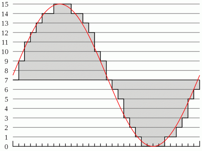
Here we go: The method I’m using works like this. We sample our desired waveform into a char array. Here’s a graphic that should make that clear.

As you can see, the waveform is divided up into samples, and the closest match in amplitude at that point is recorded as the next value in the array. There are some tradeoffs here. With more samples, you get a more accurate reproduction of the waveform, and are able to encode higher frequencies. However, as we shall see the processor has to update the output at a rate of:
period = 1 / (frequency * # of samples)
So for a 5Khz sine wave with 48 samples, the processor has to update the output every:
1 / [(5 x 10³ /sec) * 48] = 4.17 μS
4μS is only 64 clock cycles (for 16MHz arduinos), so you can see where the choice of sample rate to match your desired frequency range is crucial. To give you a yardstick, CD quality audio (you remember them, the miniature frisbee things) uses a 41.1Khz fixed sample rate, so an 8Khz tone would have about five samples per period.
Nyquist’s rule: Apparently, a dead white guy named Nyquist says that any digitally sampled waveform can be reproduced, as long as you do at least two samples per highest component frequency. I’ve never understood this result, since doing two digital samples of a sine wave will not allow you to reproduce that wave (you would have a square wave output, no?). But by that rule, doing 48 samples of our wave allows us to capture up to the 24th harmonic, which should be plenty of quality.
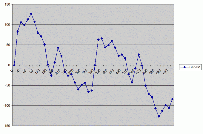
Resolution: The other consideration here is how many steps we want between 0V output and our maximum voltage. In the graphic above, there are 16 total levels, so each sample is going to consume 4 bits of memory. I opted for 8-bit sampling, which should give me good quality, and also allows me to use the conveniently pre-defined char data type. Char is a signed 8-bit datatype, so it runs from -128 to +128. I chose this over the unsigned byte, because it will make it very easy to composite two waveforms in real time– for example to mix a square wave and a sine wave, you just add the two samples together, and divide by two. When you output, you just add 128 to your sample to get the 0-255 voltage value. Here are two sampled waves. The first is a simple sine wave, and the second is a sine wave with overtones baked in as described in my prior post.
[cc]char sine[] = {0, 22, 44, 64, 82, 98, 111, 120, 126, 128, 126, 120, 111, 98, 82, 64, 44, 22, 0, -22, -44, -64, -82, -98, -111, -120, -126, -128, -126, -120, -111, -98, -82, -64, -44, -22};
//a simple sine wave with 48 samples

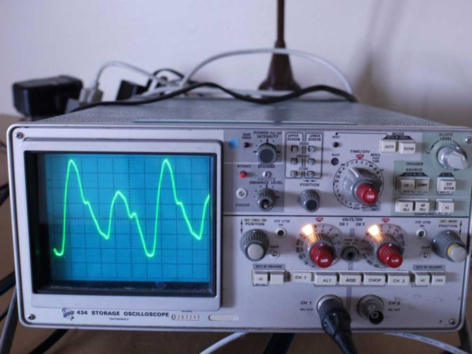
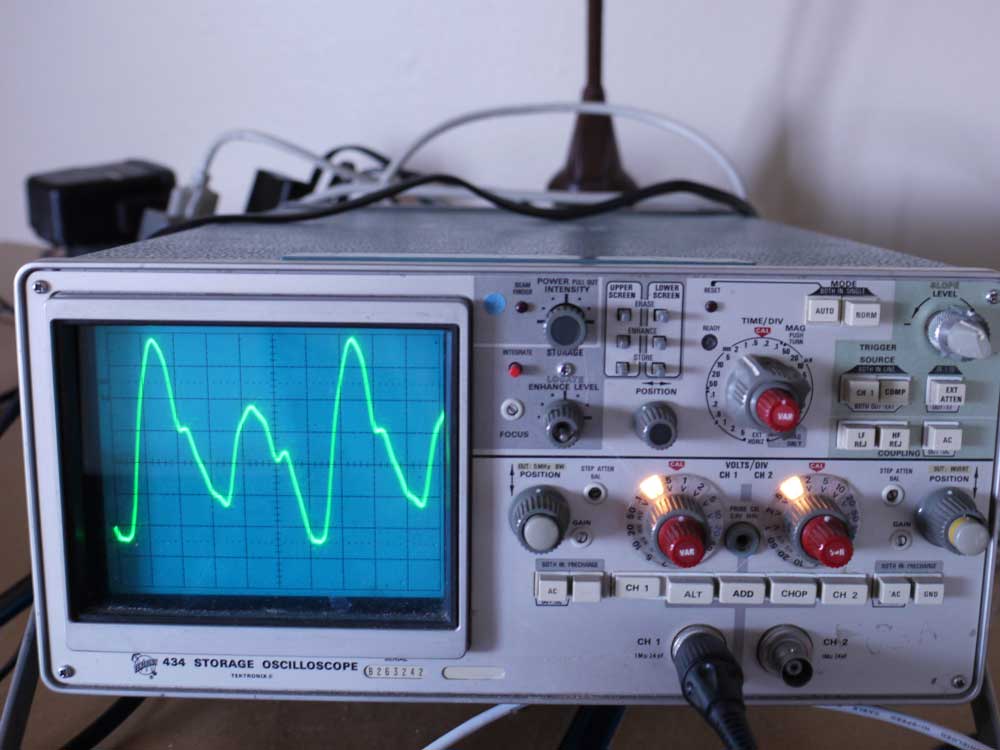
char sineovertones[] = {0,84,106,99,113,127,107,79,71,51,1,-26,7,43,23,-17,-26,-23,-43,-60,-49,-44,-66,-63,0,63,66,44,49,60,43,23,26,17,-23,-43,-8,26,-1,-51,-71,-79,-107,-127,-113,-99,-106,-84};
 //A sine wave with undertone and overtones baked in
[/cc]

Analog output: The Arduino isn’ t capable of outputting a true analog 0-5V signal. So we’re going to use Pulse Width Modulation, which was intended for dimming LEDs. Now, the default Arduino PWM frequency is 500Hz, which is useless for audio output because it’s much slower than most of the frequencies we want to generate. However, if we monkey with the control registers, we can speed it up to 62,500Hz, which is significantly faster than the audio range of 20-20,000Hz. Here’s what that looks like in code (I’m using timer2):
[cc]
/************************** PWM audio configuration ****************************/
// Configures PWM on pins 3 and 11 to run at maximum speed, rather than the default
// 500Hz, which is useless for audio output

pinMode(3,OUTPUT); //Speaker on pin 3

cli(); //disable interrupts while registers are configured

bitSet(TCCR2A, WGM20);
bitSet(TCCR2A, WGM21); //set Timer2 to fast PWM mode (doubles PWM frequency)

bitSet(TCCR2B, CS20);
bitClear(TCCR2B, CS21);
bitClear(TCCR2B, CS22);
/* set prescaler to /1 (no prescaling).  The timer will overflow every
*  62.5nS * 256ticks = 16uS, giving a PWM frequency of 62,500Hz, I think.   */

sei(); //enable interrupts now that registers have been set
[/cc]
Now the clever part: Allrighty, so now we have a quasi-analog output that we can use to play back our sound. The frequency of the output wave will be determined by how quickly we step through the array. This is an ideal application for a timer Interrupt Service Routine.
A quick primer on the timer chortle chortle chortle: Timers are complex and powerful and useful and frequently puzzling animals, but briefly: that shiny thing on your Arduino is a crystal. Quartz crystals have the useful property that when electricity is applied across them, the molecules vibrate at a very reliable frequency. Every time this frequency ticks, it triggers the processor to run one clock cycle. It’s a 16MHz crystal, so this happens every:
period = 1 / frequency = 1 / 16Mhz = 62.5nS.
Atomic clocks also operate on this principle, although they use an isotope of Cesium which is much more precise (so precise, in fact, that the very definition of time and distance are based on so many oscillations of the Cesium-133 atom).
Anyway, every time this crystal toggles, it increments a Timer Counter (TCNT) register accessed by the timers in the Arduino. When that register reaches 255 on the 8-bit timer0 and timer2, or 65535 on the 16-bit timer1, it overflows and resets to 0. So the counter timers will overflow every:
256 * 62.5nS = 16μS on timer0 and timer2
65536 * 62.5nS = 4096μS on timer1
These are not generally useful lengths of time, so we use a prescaler. A prescaler fixes it so that rather than incrementing that register with every clock cycle, we instead increment it every 8 cycles, or 32 cycles, or 256 cycles, etc. Using the right prescaler means that you can have a range of time measurement that suits your application, rather than having to load the processor down with counting timer overflows.
Now, even with the right prescaler, 255 x the prescaler x 62.5nS is unlikely to be the exact period of time we want. The nice people at Atmel have you covered, though, because each timer has a CTC Mode (Count To Clear). This register holds a user-defined value. Every time the counter register is incremented, its value is compared to this register, and if they match, the timer is reset to 0.
But that’s not all: when this match happens, a user-defined function called an Interrupt Service Routine (ISR) can be run. This is a powerful and flexible tool that can be used any time you need something to happen exactly on a specified period. Best of all, it uses no processor resources until the ISR actually runs– so your main loop() code can run happily along blinking your LED or whatever, and when the processor needs to run the ISR, it will pause it, run the ISR, and then pick up exactly where it left off. Neat.
The big caveat with ISRs is that when you’re in one, nothing else can interrupt the processor, not even another ISR, until the ISR is complete. So, for example, if you set timer2 to run its ISR every .5μS, and within the ISR you do some floating point math, and turn some pins on and off, and maybe read a sensor, your program will lock up. Since you took assuredly took longer than .5μS to do all that, immediately after exiting the ISR you’ll be back in it. The main loop() code will never have a chance to run, and eventually you’ll overflow the program stack and crash. No harm done to your hardware, but if you’re using ISRs and the Arduino stops doing anything, that’s probably why.
An example: Meanwhile, back on the farm, we were going to use the Timer1 ISR to control the frequency of our audio output. Why Timer1? Well, it’s a 16bit timer, and so if we use a /8 prescaler, the waveform array can be run as quickly as:
1 x 62.5nS x 8 prescaler x 48 samples = 24μS (although see The Big Caveat, above)
for a top frequency of 41,667Hz; or as slowly as:
65536 x 62.5nS x 8 prescaler x 48 samples = 1.57S
for a minimum frequency of .636Hz. Not that it is desirable or practical do this, but the range does cover the audio spectrum nicely. Here is a code example for the Timer1 configuration with the /8 prescaler and an initial CTC value of 160, corresponding to roughly 261.626Hz (Middle C):
[cc]
/************************* Timer 1 interrupt configuration *************************/

cli(); //disable interrupts while registers are configured

bitClear(TCCR1A, COM1A1);
bitClear(TCCR1A, COM1A1);
bitClear(TCCR1A, COM1A1);
bitClear(TCCR1A, COM1A1);
/* Normal port operation, pins disconnected from timer operation (breaking pwm).
*  Should be set this way by default, anyway. */

bitClear(TCCR1A, WGM10);
bitClear(TCCR1A, WGM11);
bitSet(TCCR1B, WGM12);
bitClear(TCCR1B, WGM13);
/* Mode 4, CTC with TOP set by register OCR1A.  Allows us to set variable timing for
*  the interrupt by writing new values to OCR1A. */

bitClear(TCCR1B, CS10);
bitSet(TCCR1B, CS11);
bitClear(TCCR1B, CS12);
/* set the clock prescaler to /8.  Since the processor ticks every 62.5ns, the timer
*  will increment every .5uS.  Timer 1 is a 16-bit timer, so the maximum value is 65536,
*  Giving us a theoretical range of .5us-32.7mS.  There are 48 samples, so the
*  theoretical frequency range is 41.7KHz - .635Hz, which neatly covers the audio
*  spectrum of 20KHz-20Hz.  Theoretical, because I wouldn't recommend actually calling
*  the Timer1 interrupt every .5uS :)  */

bitClear(TCCR1C, FOC1A);
bitClear(TCCR1C, FOC1B);
/* Disable Force Output Compare for Channels A and B, whatever that is.
*  Should be set this way by default anyway. */

OCR1A = 160;
/* Initializes Output Compare Register A at 160, so a match will be generated every
*  62.5nS * 8 * 160 = 80uS, for a 1/(80uS*48) = 260Hz tone. */

bitClear(TIMSK1, ICIE1) //disable input capture interrupt
bitClear(TIMSK1, OCIE1B) //disable Output Compare B Match Interrupt
bitClear(TIMSK1, ICIE1) //disable Output Compare B Match Interrupt
bitClear(TIMSK1, TOIE1) //disable Overflow Interrupt Enable

sei(); //enable interrupts now that registers have been set

[/cc]
Why it’s awesome:
- Since frequency control is a single value, melodies or basslines, etc. can be encoded very efficiently by storing an array of frequency values.
- Real-time waveform mixing is possible. For example, store a sampled sine and sawtooth array, then adding their values together at output. Or, use the same sine wave array with varying sample speeds to generate harmonics dynamically.
- Real-time envelope shaping can be done by multiplying the sample values by a time-varying constant.
- No external hardware besides the speaker needed, since the PWM spikes and harmonics are going to be higher than the frequency response of the speaker. It does sound better when run through a low-pass filter and audio amplifier, though.
- With the right waveform, it sounds quite decent.
Here is some work-in progress code, which takes an analog input (e.g. from a potentiometer), and uses it to control frequency.
Update: If you want this code as a zipped download, it’s here. The final product I ended up with, and the final version of the source code, is here. I recommend working with the code posted on that page, it’s better written and documentated :)
[cc]
/***********************************************************
* Arduino Audio Output                                     *
* Developed by Max Pierson                                 *
* Version Rev03 29 May 2009                                *
* Released under the WTFPL license, although I would       *
* appreciate Attribution and Share-Alike                   *
* See blog.wingedvictorydesign.com for the latest version. *
************************************************************/

char sineovertones[] = {0,84,106,99,113,127,107,79,71,51,1,-26,7,43,23,-17,-26,-23,-43,-60,-49,-44,-66,-63,0,63,66,44,49,60,43,23,26,17,-23,-43,-8,26,-1,-51,-71,-79,-107,-127,-113,-99,-106,-84};

char sine[] = {0, 22, 44, 64, 82, 98, 111, 120, 126, 128, 126, 120, 111, 98, 82, 64, 44, 22, 0, -22, -44, -64, -82, -98, -111, -120, -126, -128, -126, -120, -111, -98, -82, -64, -44, -22};
//a simple sine wave with 36 samples

int analog0 = 160; //variable used to store analog input pin 0

byte speakerpin = 3;  //audio playback on pin 3.  This can also be set to pin 11.

volatile byte waveindex = 0; //index variable for position in waveform array Sine[]
volatile byte currentvalue = 0;

void setup() {

Serial.begin(57600);

/************************** PWM audio configuration ****************************/
// Configures PWM on pins 3 and 11 to run at maximum speed, rather than the default
// 500Hz, which is useless for audio output

pinMode(3,OUTPUT); //Speaker on pin 3

cli(); //disable interrupts while registers are configured

bitSet(TCCR2A, WGM20);
bitSet(TCCR2A, WGM21); //set Timer2 to fast PWM mode (doubles PWM frequency)

bitSet(TCCR2B, CS20);
bitClear(TCCR2B, CS21);
bitClear(TCCR2B, CS22);
/* set prescaler to /1 (no prescaling).  The timer will overflow every
*  62.5nS * 256ticks = 16uS, giving a PWM frequency of 62,500Hz, I think.   */

sei(); //enable interrupts now that registers have been set

/************************* Timer 1 interrupt configuration *************************/

cli(); //disable interrupts while registers are configured

bitClear(TCCR1A, COM1A1);
bitClear(TCCR1A, COM1A1);
bitClear(TCCR1A, COM1A1);
bitClear(TCCR1A, COM1A1);
/* Normal port operation, pins disconnected from timer operation (breaking pwm).
*  Should be set this way by default, anyway. */

bitClear(TCCR1A, WGM10);
bitClear(TCCR1A, WGM11);
bitSet(TCCR1B, WGM12);
bitClear(TCCR1B, WGM13);
/* Mode 4, CTC with TOP set by register OCR1A.  Allows us to set variable timing for
*  the interrupt by writing new values to OCR1A. */

bitClear(TCCR1B, CS10);
bitSet(TCCR1B, CS11);
bitClear(TCCR1B, CS12);
/* set the clock prescaler to /8.  Since the processor ticks every 62.5ns, the timer
*  will increment every .5uS.  Timer 1 is a 16-bit timer, so the maximum value is 65536,
*  Giving us a theoretical range of .5us-32.7mS.  There are 48 samples, so the
*  theoretical frequency range is 41.7KHz - .635Hz, which neatly covers the audio
*  spectrum of 20KHz-20Hz.  Theoretical, because I wouldn't recommend actually calling
*  the Timer1 interrupt every .5uS :)  */

bitClear(TCCR1C, FOC1A);
bitClear(TCCR1C, FOC1B);
/* Disable Force Output Compare for Channels A and B, whatever that is.
*  Should be set this way by default anyway. */

OCR1A = 160;
/* Initializes Output Compare Register A at 160, so a match will be generated every
*  62.5nS * 8 * 160 = 80uS, for a 1/(80uS*48) = 260Hz tone. */

bitClear(TIMSK1, ICIE1); //disable input capture interrupt
bitClear(TIMSK1, OCIE1B); //disable Output Compare B Match Interrupt
bitSet(TIMSK1, OCIE1A); //enable Output Compare A Match Interrupt
bitClear(TIMSK1, TOIE1); //disable Overflow Interrupt Enable

sei(); //enable interrupts now that registers have been set

}//end setup()

ISR(TIMER1_COMPA_vect) {
/* timer1 ISR.  Every time it is called it sets
*  speakerpin to the next value in Sine[].  frequency modulation is done by changing
*  the timing between successive calls of this function, e.g. for a 1KHz tone,
*  set the timing so that it runs through Sine[] 1000 times a second. */

if (waveindex > 47) { //reset waveindex if it has reached the end of the array
  waveindex = 0;
  }

analogWrite(speakerpin, sineovertones[waveindex] + 128);
waveindex++;

OCR1A = analog0;

} //end Timer1 ISR

void loop()
{

analog0 = analogRead(0) + 4;
Serial.println(analog0);

}//end loop()

[/cc]
