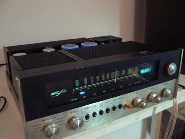
Prologue: I inherited a McIntosh 1700 amplifier from the 70’s from my grandfather. It’s an amazing piece of equipment, assembled by hand and weighing in at around 40 pounds. A few years ago, it started making a horrible buzzing noise, which from research on the internets I identified as ripple voltage from failed power capacitors. In the process of fixing the problem, I learned more than I ever wanted to know about capacitors, vintage electronics repair, and why drinking and soldering don’t mix. Sadder yet wiser from the experience, I wanted to write up a really thorough walkthrough of how to fix it if you’re having the same problem, because it might be helpful to someone and overall it was actually kind of an amazing experience for me. Drop me a line if it was helpful or you have any questions, comments, corrections, additions, rude gestures, barnyard animal noises, etc. Lezgo! But First: You will be dealing with mains voltage and large capacitors, both of which can injure or kill, the latter even after the power has been disconnected. Obviously, I am not responsible for your safety. I am not even an expert, but I will try to remember to highlight really crucial things like this. If after reading through you think this is not for you, may I suggest this guy? I decided to do the job myself but he was very helpful and knowledgeable when I talked to him on the phone. Okay, continuing!
You Will Need:
- Soldering iron and solder. I got a Weller WES51 for Christmas and it’s the cat’s fucking pajamas, y’all. But I did this project with my $15 Radio Shack model, so it can be done with that. If you’re a masochist.
- Desoldering Iron. Spend the $20 for a cheap one, it’s worth it. Also desoldering braid is sometimes useful.
- Surgical forceps (2). For use as heatsinks so that you don’t damage parts while soldering, and generally to hold things in place while you’re working on them. There are other soldering clips designs but nothing else works as well.
- Service manual. This shows the electrical schematics and lists specifications for the parts. I got mine from this dude, by e-mailing him and asking nicely. He is awesome and if I’m ever in Switzerland I will buy him a beer. Update: I recently got permission to post it online, you can download it here.
- Replacement parts. Mouser and Digikey are both great, my parts list for the MAC1700 is here.
- Multimeter with, at a minimum, AC Volts, DC Volts, and resistance measurement.
- A dremel or hacksaw, for the multisection cans.
- Beer and Johnny Cash’s Live at Folsom Prison album.
Symptoms: Ripple voltage sounds like someone saying “zzzzzzzzzz…”. It’s a constant sound that will be present as soon as you turn your amplifier on, remain constant whether you are playing music or not, but increase or decrease with the amount of volume. It will definitely sound unpleasant, and if not fixed immediately may damage your equipment. Unplug your amp and do not power it up until they have been replaced. Before we get hot and heavy with the soldering iron, you may want some explanation of what all that crap underneath the “No User Serviceable Parts Inside” does. Here’s a quick overview of how power rectification works and how to choose the right replacement capacitors.
Continue Reading for the complete walkthrough….
Okay, so you’ve ordered all your parts and they’re sitting on your dining room table in little plastic baggies, your soldering iron is warming up, and you’ve just put on your Johnny Cash and opened a beer, right? Then let’s get to it! In the Mac 1700, there are two large can type filter capacitors, a number of smaller signal capacitors scattered around the chassis, and three large multi-can filter capacitors. Screw Terminal Capacitors: I subbed the two large 4000μF can capacitors with 4800μF ones. They’re an exact physical match, but came with hospital blue vinyl wrapping, which I removed. This part is pretty straightforward, as they have screw terminals, so you just unscrew the old ones and pop the new ones in, being careful to note the polarity. I put a piece of tape with an arrow on each set, pointing towards the front of the case, to make it completely idiot proof.
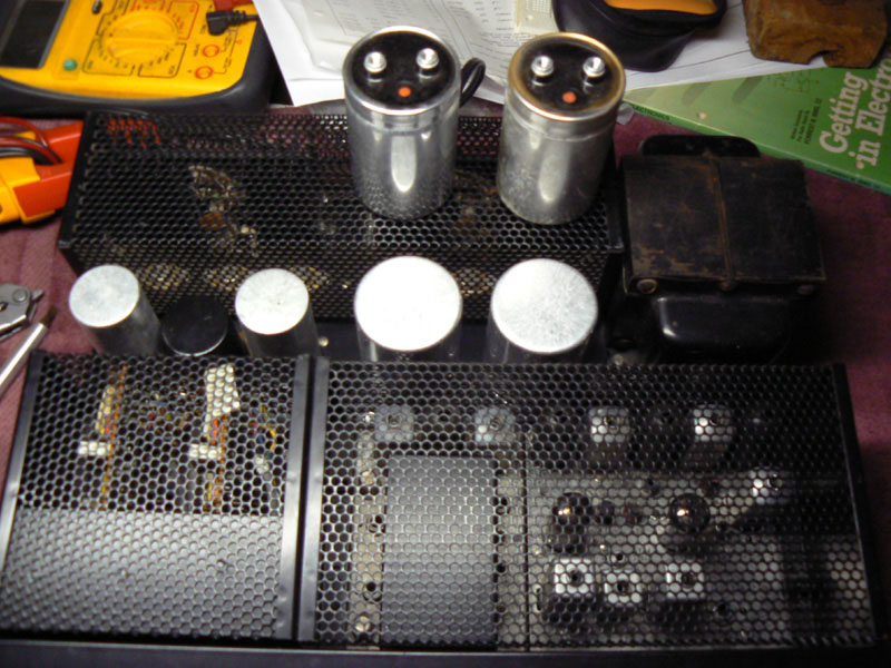
This is probably the point where I should talk about electrical safety when working with large capacitors. Capacitors store electrons, and if you place yourself between those electrons and a ground, they will shock you, and it will hurt. What makes this particularly easy to do is the fact that the entire metal chassis of the amp is the ground, much the way your car is wired. So here’s what you should do after you unplug the amplifier and before you start rooting around in there: Check the positive terminals of all your large filter capacitors with a multimeter, on DC voltage. If it reads less than 12V, it won’t shock you, but you still might fry another component by shorting it to the capacitor with your metal tools. If you have a cap that still has some juice in it, connect a 1Kohm (1000ohm), 5W resistor across the leads and let it discharge until the voltage reads zero. Signal Capacitors: These are scattered around the 1700, mostly on PCBs.
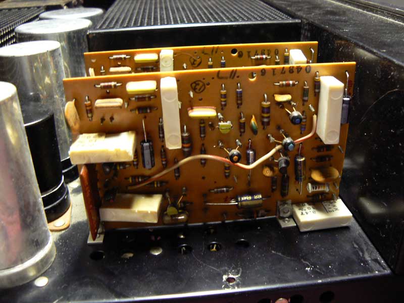
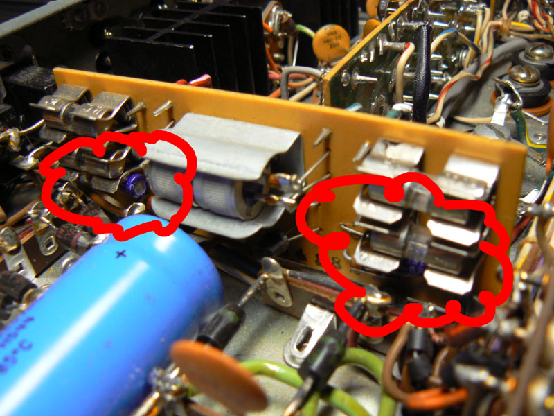
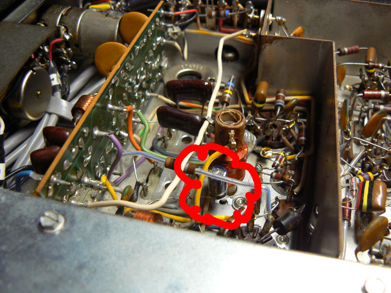
Below are pictures of caps that you might easily miss, the two bipolar caps on the power protection board should definitely be done, as well as the single electrolytic in the tube area of the amp.
Some Helpful Tips: I’m not going to cover the basics of soldering, but here are a few tricks I found helpful:
- Since these things were assembled by hand, it’s pretty easy to work on. I definitely found it helpful to unscrew the boards from the chassis, which allows you to push them around depending on what you need to get at
- If you get the surgical forceps mentioned at the beginning in the “You Will Need” section, you can clip them onto the wire for the component that you’re soldering, and the forceps will act as a heatsink, absorbing the heat of the soldering iron before it can travel up the lead and damage the component. Put the clip between the part you want to protect and the part you want to solder.
- As this is a stereo amp, there’s generally two of everything, so if you do the boards one-at-a-time you can always refer to the other board if you get mixed up.
- If you tear off about a foot of tinfoil, fold it over once or twice, you can use it to wrap up cables and other heat sensitive components before you start working in the area. That way, when-not-if your iron slips off what you’re working on, you don’t leave burn marks all over the place.
- Take lots of digital pictures of everything before you start messing with it, so you can refer to them if you need to.
- As you check/replace parts, highlight them on your service manual schematic. It will ensure that you don’t miss anything, and form a reference for you later.
- Take care to completely remove the solder from a part before you start bending the pin around, or you might start pulling the traces off the board. That is, the little copper conductive strips that are printed on the back of the board between the pins are fragile and easy to pull off.
Multican capacitors: Now we come to the fun part. And buy fun, I mean kind of a pain in the ass, but also fun in the more traditional sense. On many old amplifiers, there are can-style capacitors with more than one capacitor capacitor section built into the enclosure. On the 1700, there are three total on the left side of the amp.
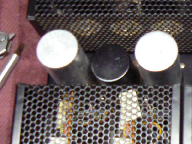
From the service manual, the specification of these are:
- Part #066-093, multisection electrolytic: 200mf/500mf, -100VDC/-75VDC, has three blade connectors, can is 3″ tall by 1 1/4″ diam.
- part #066-099, multisection electrolytic: 200mf/500mf, 100VDC/75VDC, has two blade connectors, can is 2″ tall by 1 1/4″ diam.
- Part #066-103, multisection electrolytic: 80mf/80mf/150mf/50mf, 200VDC/200VDC/150VDC/150VDC, has four blade connectors, can is 3″ tall by 1 1/4″ diam.
These are dead custom parts, and you’ll never find an exact match. Even if you found a NOS match, it wouldn’t be any good, because electrolytic capacitors degrade over time. But, not to fear: with a bit of work with a dremel you can replace these parts with higher quality
I bought replacement capacitors matching the values of the individual sections, removed the cans, cut them open and removed the existing guts, and replaced them with the new capacitors. It’s a lot of work, but you end up with a brand new capacitor that looks exactly like stock, and is easy to work on if the need should ever arise. If you decide this isn’t for you, I did get a quote from these guys, and the price was reasonable considering the work involved.
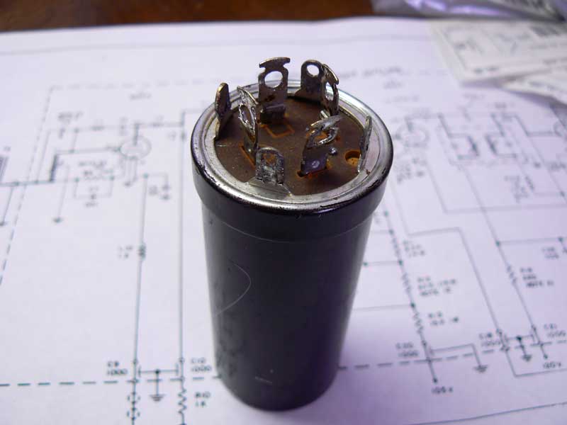
Remove the Multisection Cans: It’s a pretty straightforward process. First, while the capacitor is still connected, take pictures and notes of how the pins are oriented/connected, and identify from your schematic which pins correspond to which capacitor section. Unsolder the wires, in the center of the can, and untwist the tabs around the perimeter to release it from the chassis. You’ll end up with something like this:
Cut it Open: Carefully cut around the top of the can with a dremel or hacksaw, leaving about a 1/4″-1/2″ above the ridge at the bottom. I wrapped the can with tape, to use as a guide for cutting, like this:
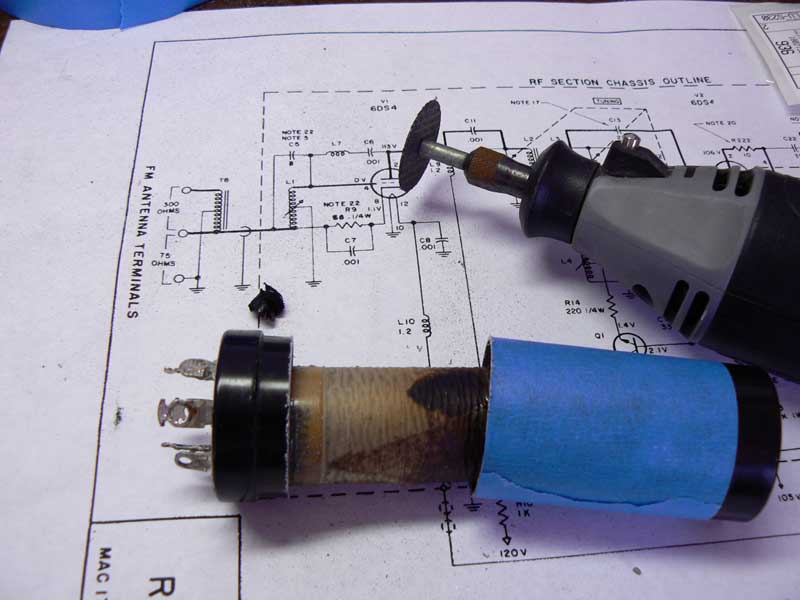
You can throw away the guts (bottom right in the picture). The top part of the can may be filled with a tar-like goop. You can boil it in water to soften it and then scrape it out, but be forewarned that this will take the coat of paint off the part as well (the aluminum will expand in the boiling water, cracking and stretching the paint). You can repaint it later, or leave it as shiny aluminum, it looks fine either way I think.
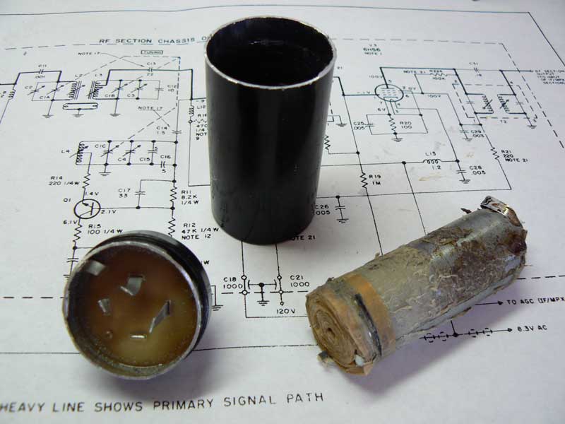
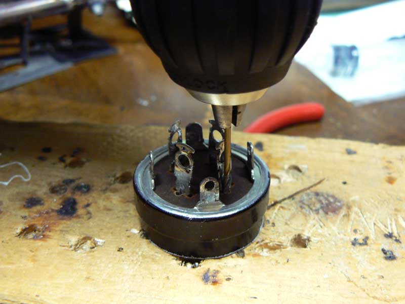
Connect the New Capacitors: You see the metal strips on the inside of the bottom section? Those are your electrical contacts. You can solder the new capacitors to those, but there’s not a lot to work with there and it seems to me that it would be a real pain to do it that way. I found a sturdier way to do it was the following. Drill new holes for the capacitor leads to pass through right next to the electrical posts, like so. Remember you will also need a slightly larger hole for the grounds to pass through.
Pass the leads of the capacitors through the appropriate holes. You should end up with something like this.
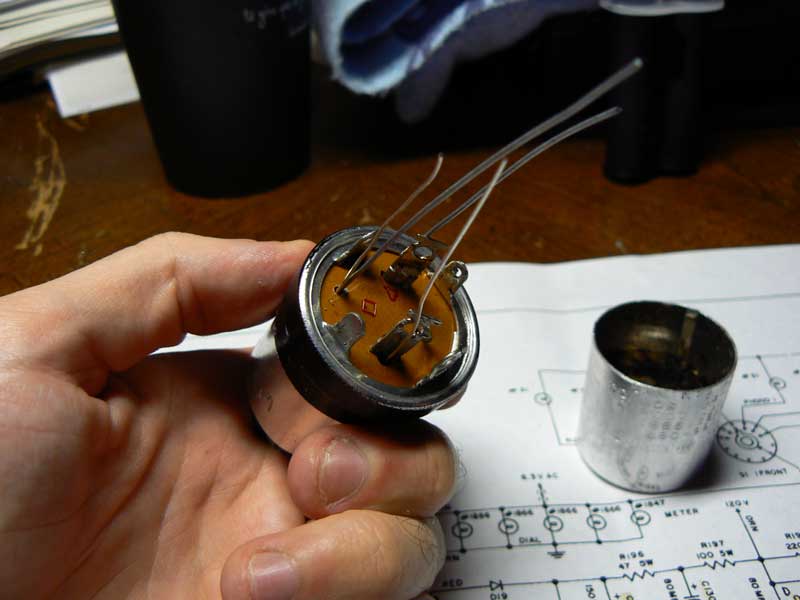
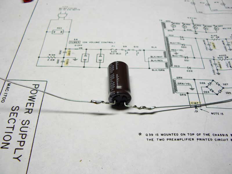
The capacitor leads will probably not be long enough. You can solder extensions on them, and then wrap the leads with heatshrink tubing so that they won’t contact each other or the sides of the can.
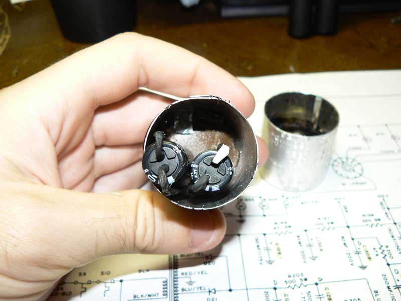
From the top, the can should look like the picture below. I reattached the top of the can by taking a strip of sheet metal about an inch wide by the circumference of the can. I laid this in around the inside of the bottom part of the can (remember when I told you to cut about a quarter inch from the flange at the bottom?). The springiness of the sheet metal was enough to hold the top part of the can firmly on, it looks completely stock, and I can easily remove it if I ever need to service what’s inside.
Reinstall the cans, solder the leads in in the appropriate places, and you’re done! Your amp should provide many more years of faithful service. Special thanks to the peeps over at the Audiokarma.org forums, who patiently answered all of my questions.
I am in the process of rebuilding my Mac 1700, I was the original owner.Did you just replace the the five (5) .47uf /250 volt caps on the preamp board or others ? Outside of replacing the caps you indicate are there any others I should replace ? Should I replace the power transistors ? I gave Mac to my Nephew about 25 Years ago and he had it stored in a crawl space and abused it. When I got it back I was in very poor shape. Now I took it apart, repainted the chassis, etc .Got a new face plate from Audio Classics, I hope I will turn out like new.
I am learning my way, Any Suggestions you have is appreciated.
Vince Serritella
St.Charles ILL
Hello Mr. Max Pierson-Liénard…regarding the ‘Connect the New Capacitors:’ I don’t believe you can solder to the underlying strips as they are made of ‘aluminum’, coming out of the capacitor. Hence, your method of drilling the small holes is brilliant. Bless Your Bunions!
Hi,
I’m in the process of replacing some capacitors on my MAC 1700 and saw your comment about the two bipolar capacitors(SC 41F GE 7213G) I could not find a replacement or equivalent and was wondering what you have used. It’s so nice to find people like you on the web. Thank you so much.