I wrote this up as part of my guide to re-capping a vintage amplifier, but figured it was useful and self-contained enough to stand on its own as a post. The examples are from that project, but the principles are general. Most of the electrical devices that you use every day are powered off AC, but operate on DC. Newer electronic devices often have switching power supplies, which is why the wall warts have gotten noticeably smaller and lighter. But larger or older devices will have the step-down transformer + rectifier + filter capacitor combination, which is what is described here.
First, Transformers: here are three stages to converting the AC in your wall to the DC in your amp. The first is your power transformer. This converts the 110V AC to a lower voltage AC, or several lower voltages. It also smooths out some of the spikes and dips in your ac line.


Side note about the transformers in vintage amplifiers: Usually, this is a dead custom part unique to the manufacturer and model number. If the transformer is damaged by another part failing or not being installed properly, you will never find a new replacement, for love or for money. Your only option will be to cannibalize an identical vintage amp for the part, which is abhorrent on philosophical as well as financial grounds. So be careful, mmmkay?
Secondly, Rectification: the power enters the Rectifier, which flips the negative part of the wave over, so that the voltage is all positive, even if it’s still pretty bumpy and unusable to power an audio signal.

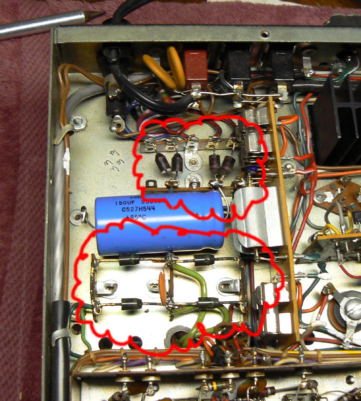
If your filter caps are bad, that wave on the right side is actually the buzz you’re hearing. On the 1700, there are two rectifiers, shown below.

A Rectifier is Composed of Four Diodes. Diodes, the four black cylinders in the bubbles in the above picture, and the four triangular symbols in the figure, do occasionally go bad and should be checked. You can sometimes check them with a multimeter, but they take .6V to start conducting electricity, and sometimes the amount of voltage a multimeter puts out for the continuity check is less than that, so they’ll test as not passing current. Also, if your capacitors are good, there can be voltage in the system, which can screw up your readings or even damage the continuity tester.
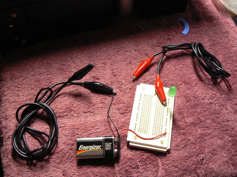
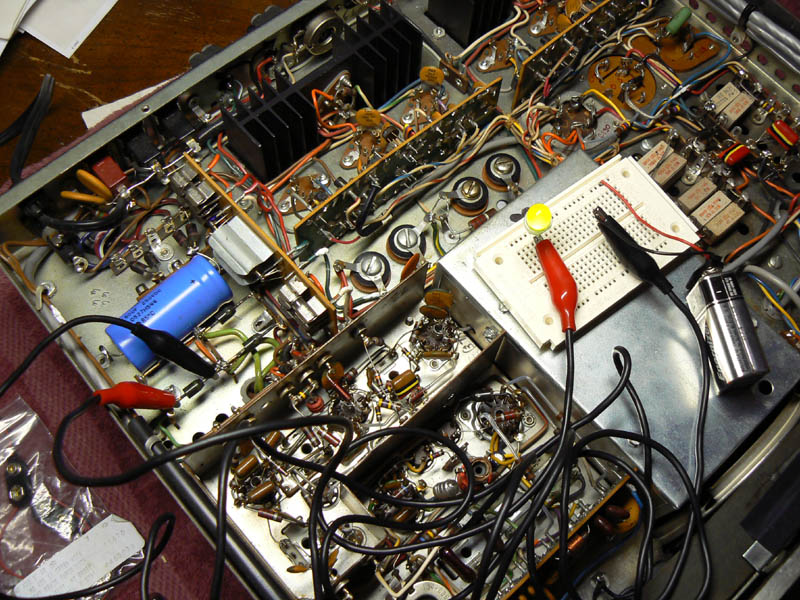
So a better quick and dirty check is to wire up a 9V battery and a small light bulb, and connect it across each diode, like so:

In the example shown I used an LED. The LED shown has an integral (built-in) resistor, but otherwise you should use a 1K 1/2W resistor if you use an LED, to avoid putting too much power through the system and probably zapping the LED, if not the diode itself. Once you clear the .6V threshold, a diode provides no resistance to the current flowing through it, so it’s just like connecting the two poles of the battery to each other directly.

Diodes are marked for polarity by a stripe or tapering or dot or whatever on the positive end. The light should light up when you have the positive terminal (red clip in the picture above) attached to the marked end of the diode, and the negative end (black clip), and only then. Due to the presence of capacitors in the system, it may briefly light up the other way, but it will not stay on. If it lights up both ways and stays on, it’s bad. If it doesn’t light up either way, it’s bad. A diode failure can do a lot of damage, best practice is to replace them, bad or not.
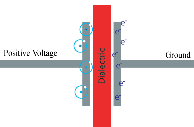
Finally, the Ripple Voltage is Smoothed out by the Filter Capacitors. You can think of a capacitor as a bucket ‘o electrons. All capacitors have two layers of conducting material, with a layer of non-conducting material between. The non-conducting material is referred to as the dialectric. What makes a material conduct is that it has a large number of possible electron configurations, so that at any time in a metal there are a cloud of loose electrons wandering from atom to atom. When you apply a positive voltage to one side of the non-conducting plate, it pulls electrons off of that plate, much like lower air pressure in a room that you’ve just taken the air pressure out of (electrons are negatively charged, and so they are attracted to a positive voltage). The lack of electrons on the positive plate induces a greater number of electrons on the negative plate, giving it a net negative charge.

The astute reader will notice that as the electrons are actually travelling towards the positive voltage. The direction of current travel shown in most electrical schematics is actually the opposite of the direction of charge carrying particles. We have Ben Franklin to thank for this incorrect convention, and in some European schematics, particularly older ones, the current orientation is shown correctly.
So anyway, when the rectified voltage coming out of the rectifier hits the capacitor (bucket ‘o electrons), it tends to place electrons in the capacitor when the voltage peaks, and pull electrons off of the capacitor when the voltage drops. This has the effect of smoothing out the voltage wave so that you get clean DC power.

There is still some variation of voltage on the right side, and the variations in current resulting from this varying voltage is referred to as ripple current. Clearly, ripple current is a problem for audio applications, as it will come through the speakers as a 60Hz buzz. A good amplifier will minimize this effect by using larger capacitors, but there are some trade-offs.
The biggest is that when you turn your amp on, the capacitor is essentially a black hole that will accept a large amount of electrons very quickly. This means that initially a large current is traveling through your transformer, which stresses it. Much of the reason why quality amplifiers are so goddamn heavy is due to the transformer having been upsized to withstand the larger capacitors.
The other issue here is one of diminishing returns. Doubling the size of the filter caps from their designed rating will probably do nothing for you, because as long as the 60Hz tone from the ripple current is below the level detectable by human hearing, there’s no advantage to reducing it further. The point I’m making here is that people will tell you to ‘upgrade’ your amplifiers 4,000mF filter caps with 10,000mF caps, but they are incorrect and you shouldn’t listen to them.
Max,
I have a MAC-1700 as well, and I just wanted to let you know I love your website. It’s been very useful and informative in learning about my amplifier.
I was wondering if you could answer a question for me. I take it that the transformer in a MAC 1700 is a “step down” transformer. My question as this:
If this type of transformer were to fail, can it be rewound/repaired, specifically for the MAC -1700?
If so do you have a recommendation for who rewinds them?
Thank you,
Hi Crawford,
Glad you found it useful. The transformer in the MAC-1700 appears to be custom to me– it has multiple low voltage taps out of it which are odd voltages like +/- 37V. I don’t know who would do that work, you could call stereo repair shops and get a referral since they probably don’t do that in-house?