For a project I’m working on, I want some functionality to be triggered by touching a metal plate. Actually, I would ideally like the user to be sensed from several inches away, before they even touch the plate. This should be possible by measuring the capacitance of the plate, as an object (such as your hand) approaches it, it creates an electrical field between the electrons on your hand and the electrons on the plate. In practice, every time I’ve tried to make this sensor type work in a project I’ve found it to be too unreliable for use in production. I wanted to see if I could improve the stability and accuracy of the measurements and, in the way of these things, fell down a real rabbit hole. Let’s get started, shall we?
The Theory
The general equation for capacitance is:
C = εA/d
Where A is the area of the two objects, d is the distance between them, and ε is an experimentally defined constant that varies by the dialectric type, in our case the dialectric would be air. So as the distance between your hand and the plate approaches zero, the capacitance increases linearly. Alternatively, you could increase the surface area of your hand for the same result, but this is harder for most people.

Well okay professor, but there’s no capacitance input on an Arduino, so how do we measure this? In practice, any capacitance meter uses a resistor-capacitor (RC) circuit to measure capacitance indirectly. A capacitor can store charge when you apply voltage to it. So if you use a resistor to limit the amount of charge that can reach the capacitor per unit time, the capacitor will charge slowly, according to this equation:
τ = R * C
Where R is the resistance, C is the capacitance, and tau is referred to as the time constant– at 1τ the voltage across the capactor will be about 63% of the applied voltage. So if we have a fixed value for R, and we know the voltage applied, we can measure the capacitance indirectly.
So is all of this theory true or is my physics textbook full of lies? Let’s find out.
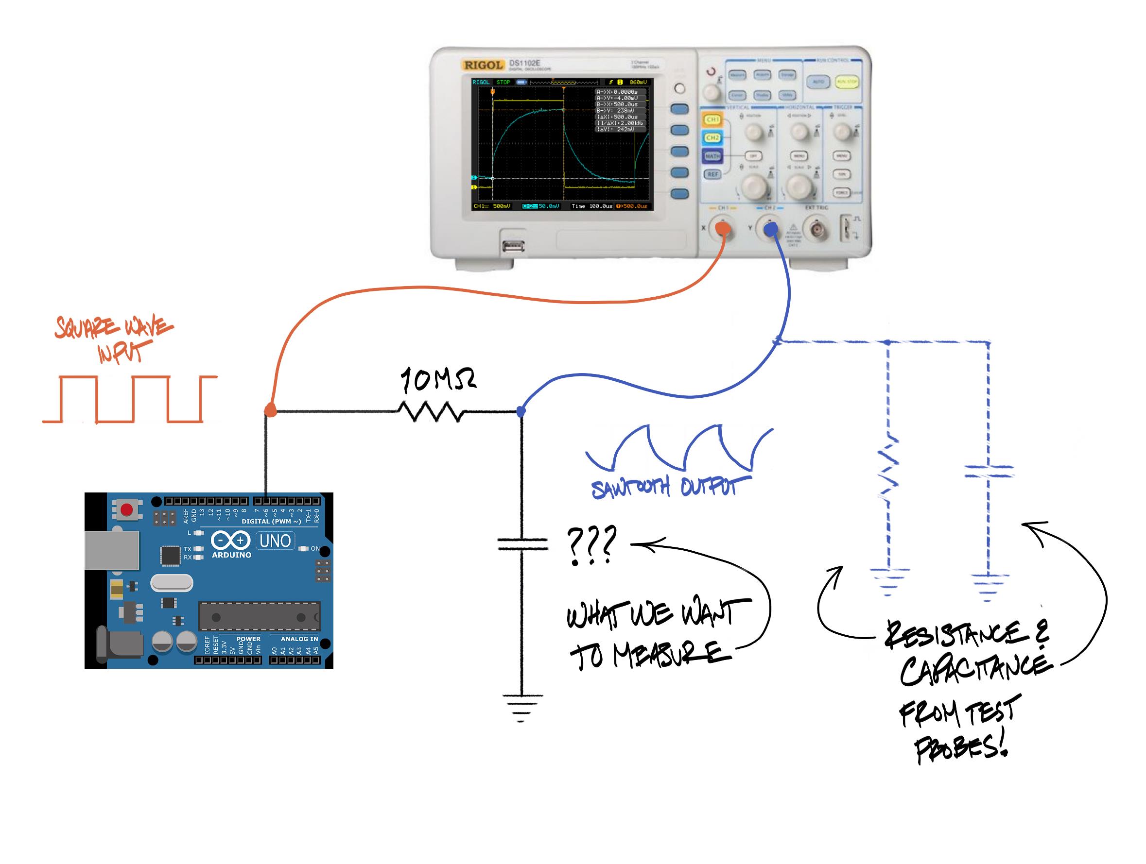
As a cheap and cheerful function generator, I used the Arduino running the Blink sketch. I ran that square wave through a 10MΩ resistor, and then measured the charging time of the capacitor on the other side of the resistor. This worked fine for larger capacitance values, but I ran into some really thorny practical issues when I tried to measure the capacitance of the metal plate.
In practice, theory is worthless
So the first issue is that the capitance that we’re trying to measure is really, really small. How small? The plate I’m using is about 2″ x 4″ or 4 x 10⁻³ sq m. If I want to be able to measure with my hand starting about 6″ or 0.15m away from the plate, and the permittivity of air ε is 8.86 x 10⁻¹² F/m, then from the first equation at the top of this post:
C = εA/d = (8.86 x 10⁻¹² F/m * 4 x 10⁻³ m2 ) / .15m =
2.36 x 10⁻¹³ F = .236 pF
Actually, we can graph it over the distance:
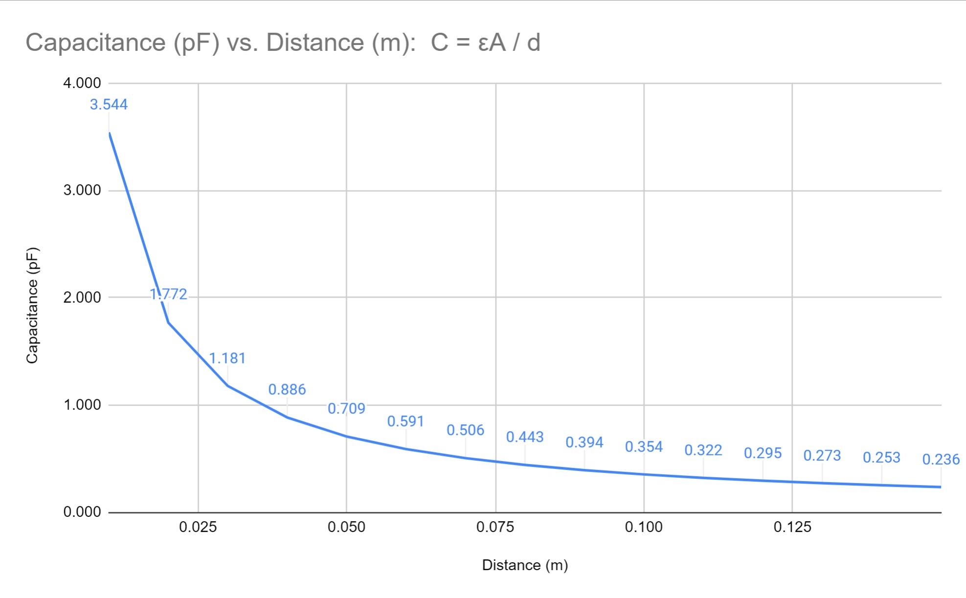
So .236 pF is .2 trillionths of a Farad. Now, a common capacitor might be in denoted in microFarads (millionths of a Farad), but this is a millionth of a millionth of that. My multimeter is theoretically capable of a .01 nF resolution which is still 100x what we are measuring here, but in practice sits at about 0.33 nF with just the leads connected (probably due for calibration idk).
So it’s going to be challenging to distinguish that tiny difference in signal from background noise. But working with that second equation again we do have an option here: if we use a huge resistor, say 50MΩ or so, we can slow the charging time down to offset the tiny capacitance.
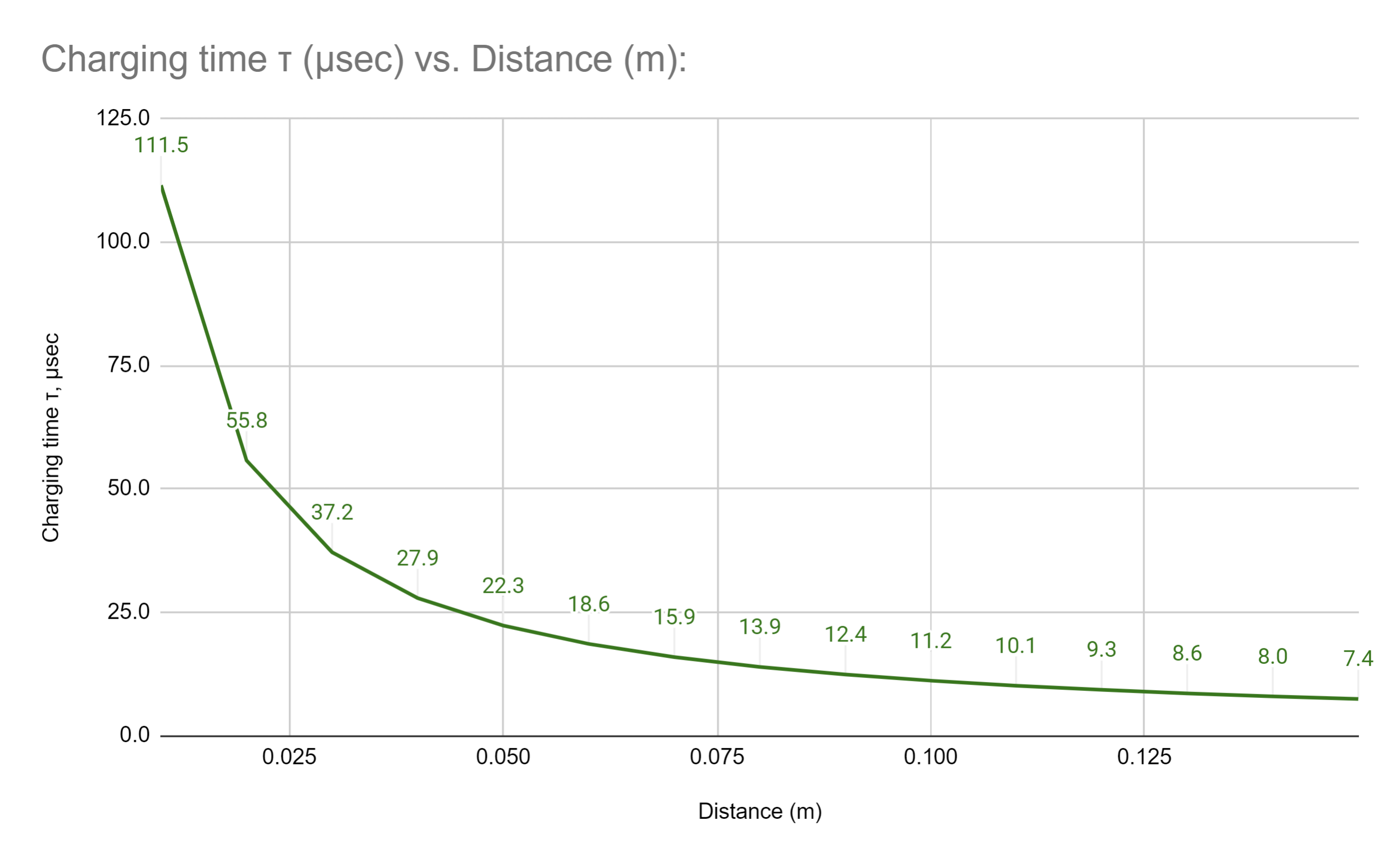
At the right hand side of the graph we need to distinguish times on the order of .6 μsec, which is difficult on a standard Arduino with a 16Mhz clock– in fact, the micros() function will only return multiples of 4 microseconds. To make things easier, we can put a 10pF capacitor in parallel with our plate (i.e. from the receive pin to ground) so that we have some “base” capacitance built in, this will put a bit of a floor under the measurements and make it easier to measure.
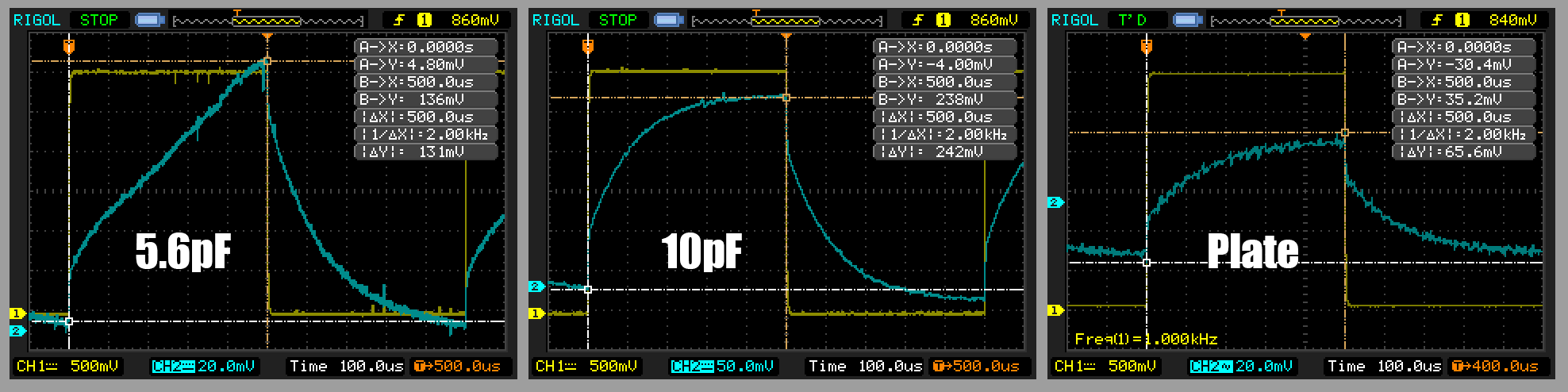
By measuring the base capacitance of the system and then subtracting that out, and using the averaging function of my oscilloscope, I was able to get measurements even for very small capacitors that were pretty close to what the theory predicts, and isn’t that what science is all about?
But Now We Have A New Problem
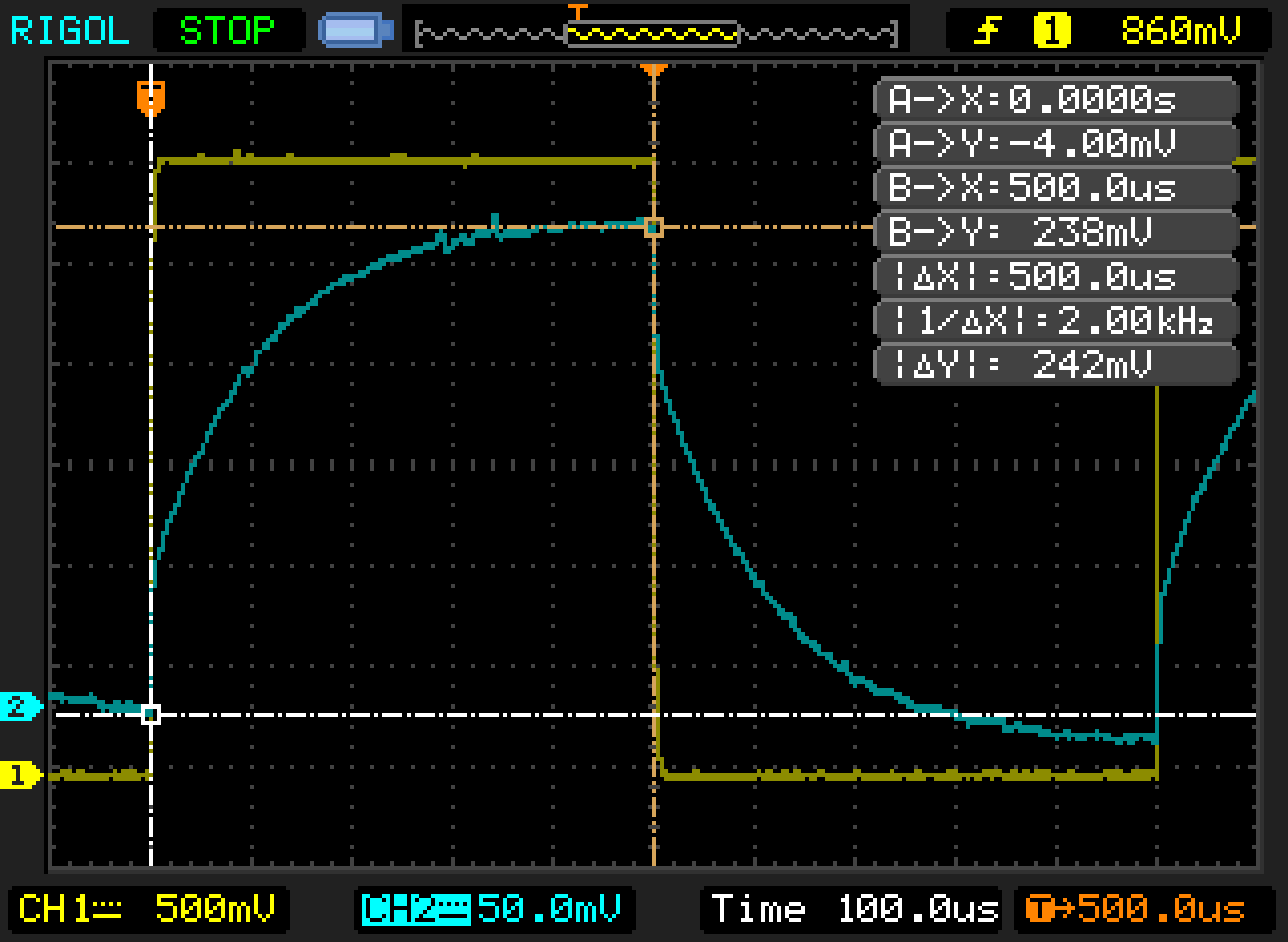
Because we’re charging our capacitor through a 50MΩ resistor, and that capacitor is a foil plate attached with a somewhat lengthy wire, we’re going to get all sorts of electromagnetic interference– the voltage of the foil plate is only *very* loosely tied to the charging pin, and is free to flop around to whatever voltage is induced by nearby electrical fields. For example:
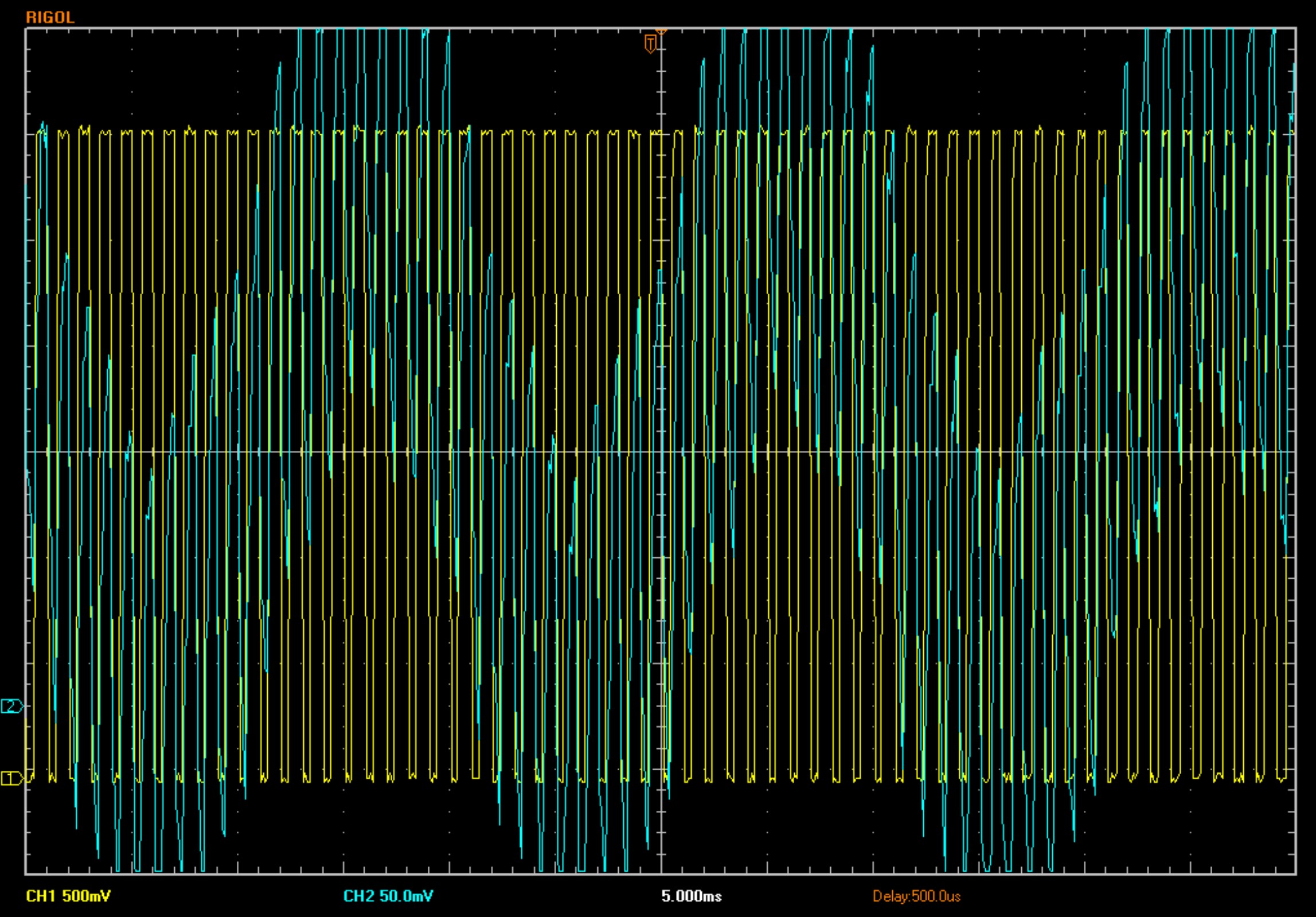
The yellow trace is our square wave. The blue trace is the resulting voltage at the capacitor, which is separated from the square wave by a 50MΩ resistor. That suspiciously sine-wave looking wiggle is occuring at… you guessed it: alternating current frequency. On an oscilloscope, we can set the trigger to our nice consistent square wave, and then use averaging to counteract the bumpiness of the readings induced by the AC current. On an Arduino, we’ll have to be aware of this issue and write some software to manage it.
Which brings us to…
The Arduino CapacitiveSwitch Library
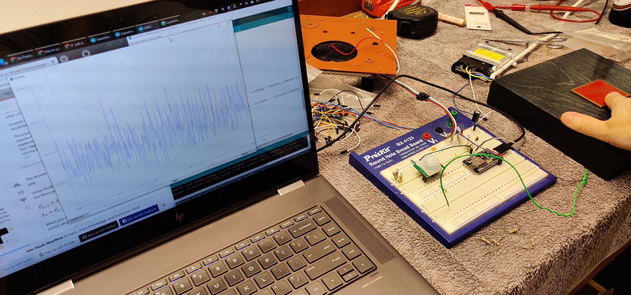
For starters, I tried out the CapacitiveSwitch library in the Arduino Library Manager. I wired up the circuit per the instructions, but I had this really bumpy output:
I was seeing maybe 2-3 samples at values that seemed “reasonable” and then the values would spike up to 10 to 100 times that before dropping down again, with a very consistent frequency. The capacitiveSwitch library is supposed to have some averaging functionality built in, but I was seeing this behavior no matter how I adjusted the physical values of the circuit or the software variables such as number of samples. Here’s a close-up of the graph:
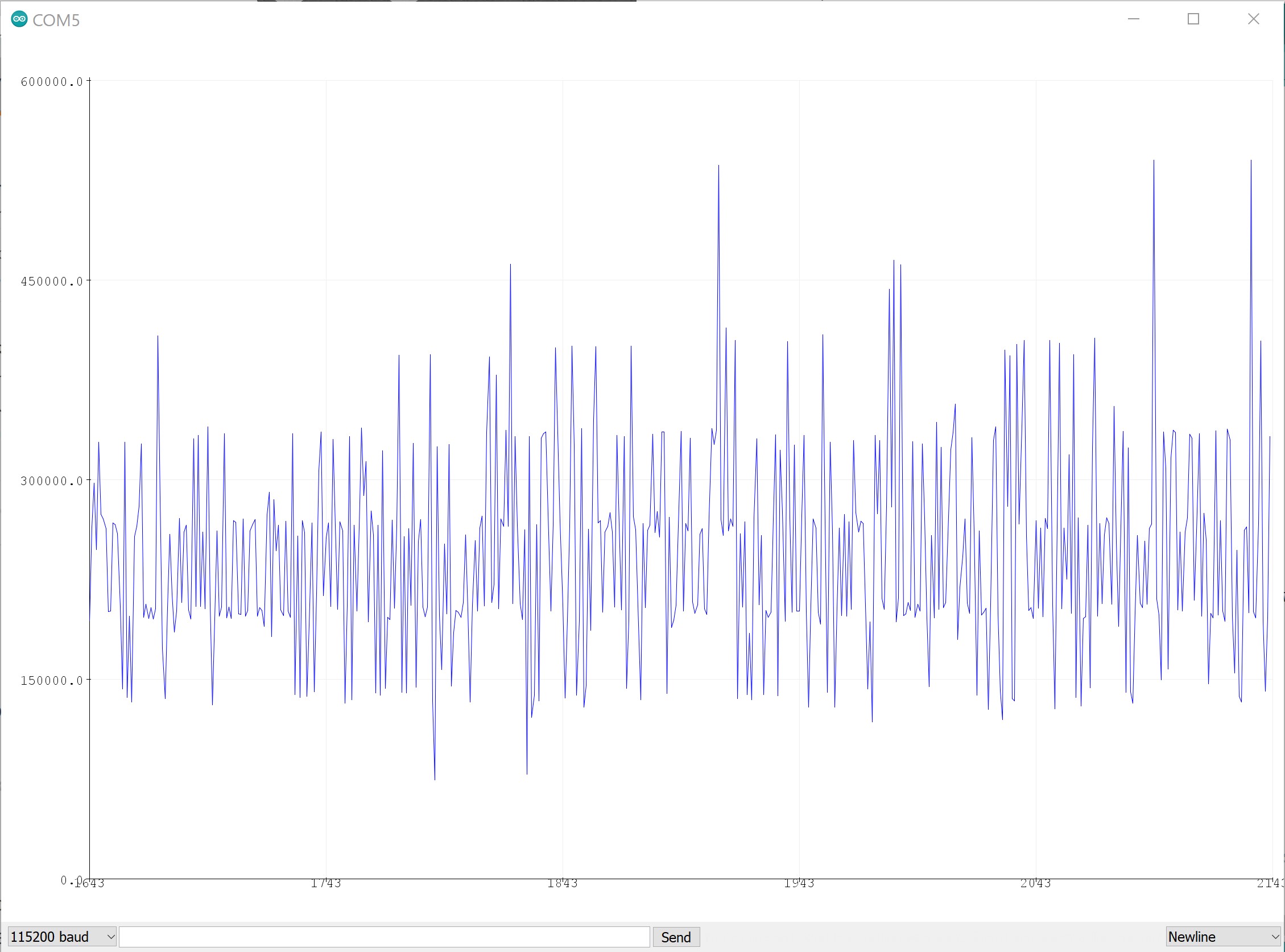
you can see that there are really more like four values here and the output is bouncing between them– there’s a consistent value at 15000 or a little less, two more between 15000 and 30000, and another one at maybe 35000. If it was just noise from the signal you wouldn’t have these consistent horizontal bands running across. So now we have two options:
1. Ragequit
or
2. Analyze someone else’s code to figure out why it’s not working
Both fine options, really. I went with the second one.
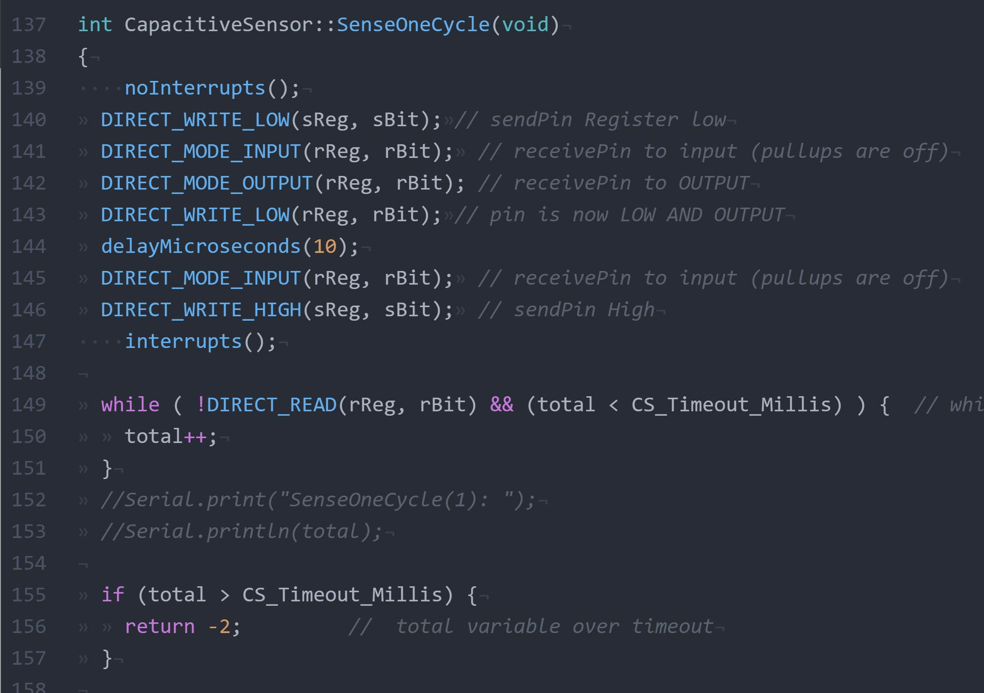
Digging around in the libray file, it looks like we set up the pins, and then we just hang out in a while() loop incrementing a counter until the receive pin flips over to high. Since that could potentially be forever, there’s a timeout and if the timeout is exceeded, the function returns -2. There’s a couple decisions here I don’t understand, e.g. why turn off interrupts while configuring the pins, but not for the while() loop which is the actual critical timing function. But anyway, clearly this is a *very* crude algorithm. I guess if we need to resolve timing on the order of a microsecond on a processor which only has 8 or 16 clock cycles per microsecond, it’s maybe as good as it gets.
Or anyway, it was as good as it gets when I started working with Arduino. Today, we have the NodeMCU with an ESP8266 on board, which has an 80Mhz(!) processor, plus a full Wi-Fi stack(!!), all for about $10/unit(!!!), or 1/4 what I paid for my Arduino Duemilanove which was hot shit in 2009. Fucking kids don’t know how good you got it.
There are some hardware limitations with the ESP8266 that I’m going to cover in a separate post, but since we have a much faster processor, we’ll use a proper hardware interrupt instead of camping out in a while() loop like the CapacitiveSwitch library does. This has the added benefit of being non-blocking, so the arduino can do other things while it’s taking a reading. You can get the latest version of the code here.
//NODEMCU board.
#define SEND_PIN  D2
#define RECEIVE_PIN D6

//328 based.  Note that only some pins can have interrupts attached
//#define SEND_PIN  4
//#define RECEIVE_PIN 2

/* capTimer: time of changed state.  Set to 0 to take a new reading.
 * capLast: the last recorded capacitance
 */
volatile unsigned long capTimer = 0;
volatile unsigned long capLast = 0;

void setup() {
  Serial.begin(115200);
  Serial.print("Booted");

  // Set LED to off (internal LED is inverted)
  pinMode(LED_BUILTIN, OUTPUT);
  digitalWrite(LED_BUILTIN, HIGH);

  //capacitive input setup
  pinMode(SEND_PIN, OUTPUT);
  digitalWrite(SEND_PIN, LOW);
  pinMode(RECEIVE_PIN, INPUT);
  delay(100);
  // Set receive pin as interrupt, assign interrupt function and set RISING mode
  attachInterrupt(digitalPinToInterrupt(RECEIVE_PIN), receivePinISR, RISING);
  capSensorSetup();

}//end setup

void loop() {

  if (capTimer == 0) {
    //discard very small values, as we are interested in large fluctuations caused
    //by EMI from the AC sine wave
    if (capLast > 50) {
      digitalWrite(LED_BUILTIN, HIGH);
      Serial.println(capLast);
    }
    capSensorSetup();
  }
  else if (micros() - capTimer > 10000) {
    //check to see if we missed the interrupt for some reason
    if (digitalRead(RECEIVE_PIN) == HIGH) {
      digitalWrite(LED_BUILTIN, LOW);
      Serial.println("Aborting sensor read");
      capSensorSetup();
    }
  }


}//end loop


/*
 * set up the capacitive sensor pin to take a reading
 */
void capSensorSetup() {
  //DEBUG_PRINT("capSensorSetup()");
  digitalWrite(SEND_PIN, LOW);
  delayMicroseconds(10);
  /*  Here's a hacky solution for taking a reading at the same point
   *  in the AC sine wave (at 50Hz) - use this if you actually want to
   *  measure capacitance, as opposed to EMI, which is more stable
   *  in my testing.  See blog post.
  if (capLast < 20000) {
    delayMicroseconds(20000-capLast);
    }
  else {
    delayMicroseconds(20000);
    }*/
  capTimer = micros();
  digitalWrite(SEND_PIN, HIGH);
}


// Interrupt Service Routine for capacitive sensor
ICACHE_RAM_ATTR void receivePinISR() {  //NODEMCU
//void receivePinISR() {                //328 based arduino
    //if capTimer has already been set to 0 by this routine, don't run it twice
    if (capTimer != 0) {
        capLast = micros() - capTimer;
        capTimer = 0;
    }
} //End ISR
So this is interesting. With this new code, we get a very precise readings, which is not to say accurate. We have maybe 10-12 readings at a consistent level, punctuated by repeated spikes to a much higher level.
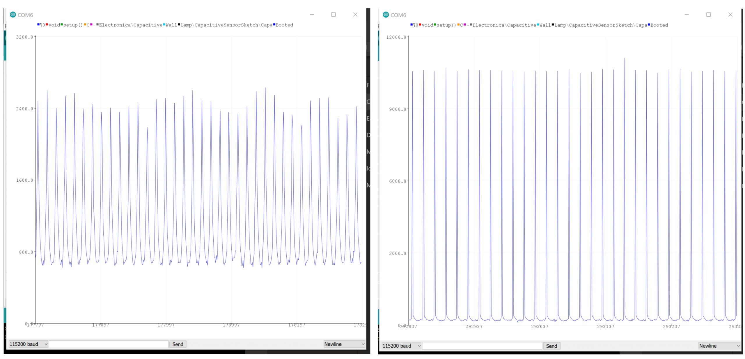
Furthermore, as I move my hand towards the plate, two things happen: The typical reading drops towards zero, but at the same time, the magnitude of those spikes increases by 4x to 5x. Here’s a video of my oscilloscope as I move my hand towards the plate showing the same behavior:
Those big spikes in the former graph are large increases in charging time, which as you can see from the oscilloscope are occuring regularly every 20ms – it’s picking up the 50Hz AC wave and the electromagnetic interference is stronger than any effect of the charging pin. At least in my testing, that EMI also behaves roughly linearly with distance, and is in fact a stronger and more consistent effect than the capacitance we came here to measure. I live in a 1920’s building without any grounding whatsoever, I would be interested to know if it’s different if you’re in an environment that complies with modern electrical codes.
So what did we learn here?
We have two phenomena that show up on our sensing pin, a change in capacitance and an induced voltage caused by the charging pin acting as an antenna. Either are potentially usable as a sensor input, but for the best stability of measurements you’ll want to filter for one behavior or the other. For example, if you want to sample capacitance you could time your code to take readings at the same point in the AC sine wave, and discard any measurements over a threshold based on the expected capacitance of your system. I would imagine most people are more interested in having a sensor that reacts predictably and repeatably, and in my testing the interference from AC was actually more robust. In which case you’re looking to filter out very short measurement times and to better focus on the magnitude of those large spikes in charging time induced by AC EMI.
The other takeaway of this post is that the default CapacitiveSwitch library isn’t much more than a proof-of-concept code, and it shouldn’t be used for a real project where you’re trying to get something that will work consistently. As convenient as the Arduino library system can be, I think it makes the underlying code opaque for most users as the actual mechanisms get buried in another file in another location on your computer. In the case of the CapacitiveSwitch library, since the code isn’t much more than a while() loop, the user would be better served if it was just placed directly in the sketch file similarly to the simpler examples like Blink().
Hope all this was useful, please do leave a comment or push a commit to the github repo if you have ideas for improvement.