 Lately I’ve been using my 5V Arduino in concert with 3.3V devices via i2c, and so I’ve found myself requiring an interface part to convert the two logic levels.
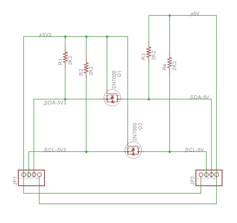
I had previously done this on the breadboard with two 2N7000 MOS-FETs according to this Philips application note AN97055:
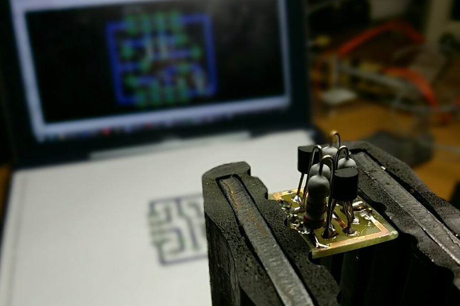
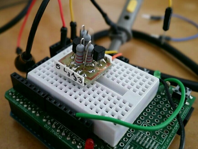
This worked, but it was a lot of parts to set up on the breadboard each time, and I wanted something hardwired so that I could focus on other things when it came time to troubleshoot. So I cooked up this little guy:
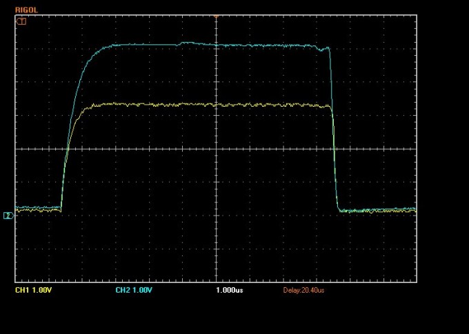
Testing the waveform with an oscilliscope, you can see some noise is introduced on Channel 1, but I always wonder in these cases how much of that is just because I have a bunch of probes stuck everywhere– the act of measuring changes the measured behavior and so on. But, it should be perfectly adequate for prototyping purposes.
Downloads:
If you’d like my Eagle files to incorporate this into your file, 3V to 5V i2c Eagle Files.
A pdf ready to etch is here: 3V to 5V i2c Eagle Files Level Shifter Rev0.
One note: if you look at the pictures of the finished product, you’ll see that rather than the usual way of doing things where you put the PCB on the bottom plane, then drill through and put the components on top, I’ve instead mirrored the layout, and soldered the components on the top plane.
I did that so that I could solder the pin headers on top, as you can’t solder them to the bottom traces because the plastic connectors get in the way. If you download the pdf I linked to, it’s already been flipped and is ready to go. If you download the eagle files, make sure you select “mirror” from the print options.
Hope it comes in useful for you!