Thanks for nothing, Vivian Maier: So this starts with a trip to Chicago. While we were there, we visited the Chicago History Museum and it turns out they’re a little butthurt about the whole Second City thing, but anyway the main attraction was a Vivian Maier exhibition, which blew my mind.

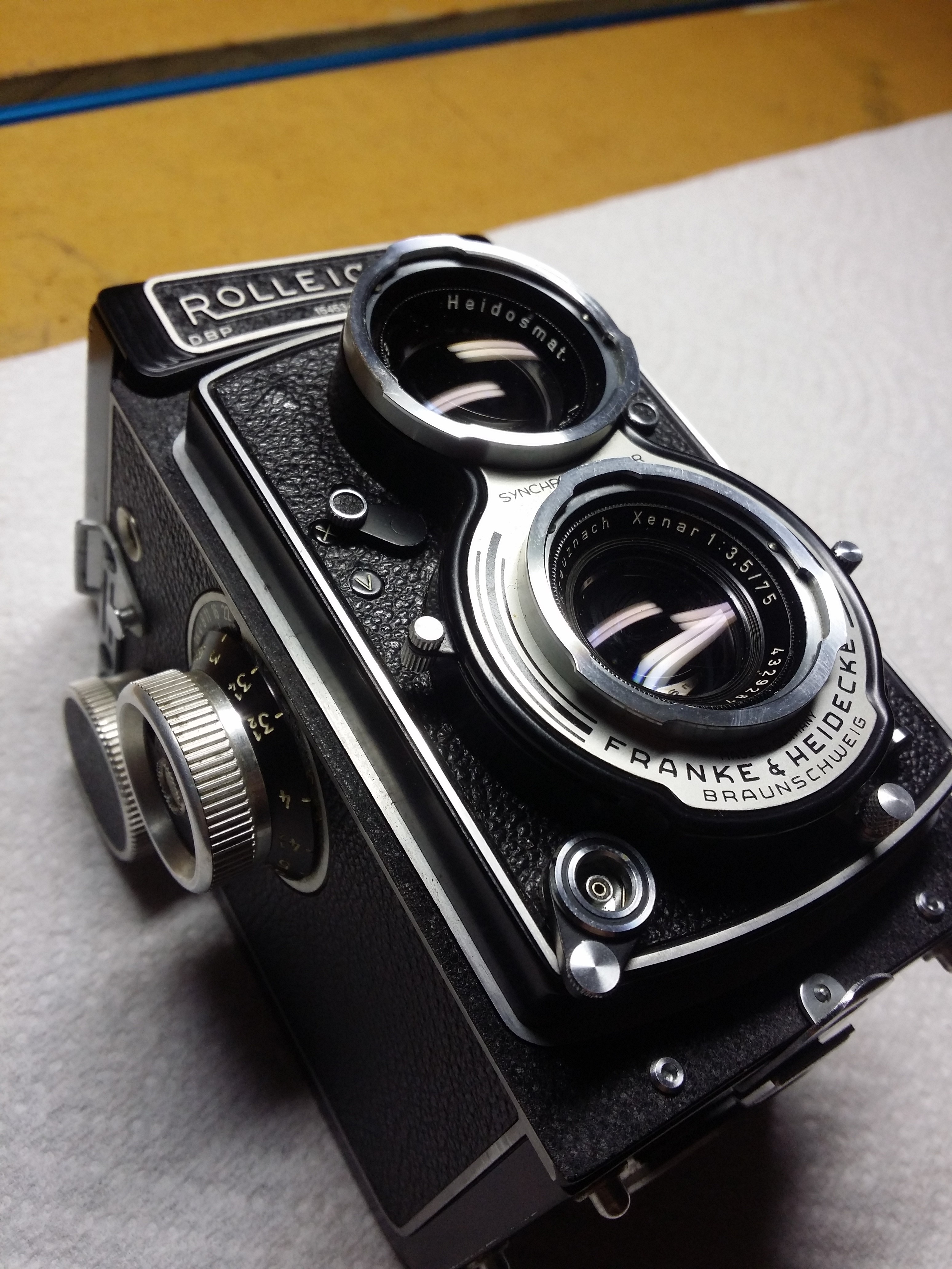
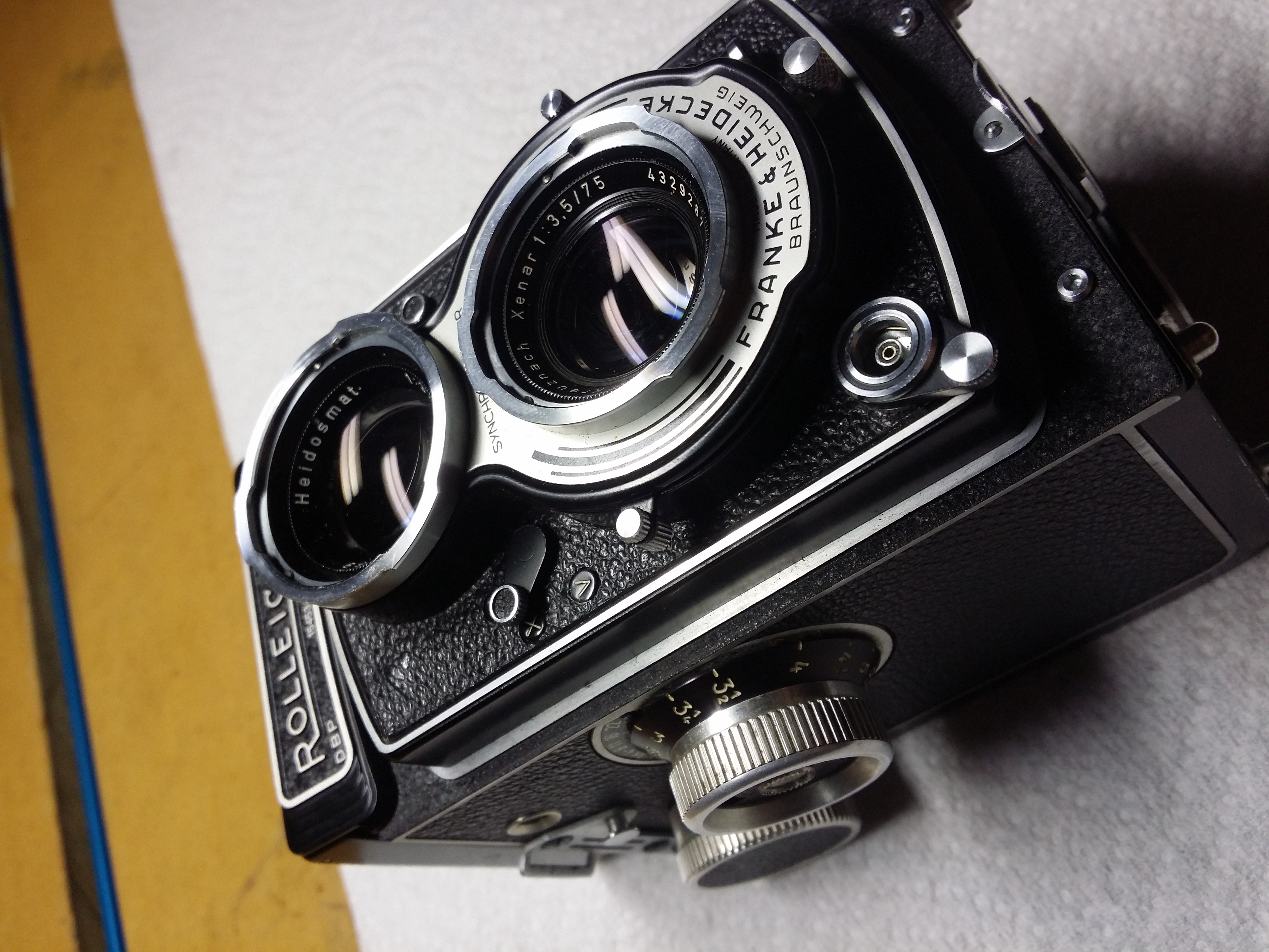
So long story short I got all inspired and bought a twin lens reflex camera on the ebay, a Rolleicord Va. I’ve shot on medium format but I’ve never tried to work with a Nifty Fifty focal length before, but I like the way it forces you into an editorial mindset– the field of view isn’t very large, and you have to make choices about what you’re going to include.
But: Unfortunately like most cameras that are 60+ years old, the one I bought had a sticky shutter. If I warmed up the shutter by test-firing a few times it would work fine, but if allowed to sit or in cold weather it would randomly stick open. Which isn’t something that you want the camera shutter to do, for all of you budding photographers out there. The remedy is a shutter overhaul performed by a professional camera repair technician, which will be a strange older guy with a wizard beard.
So I decided to get right in there and do the shutter overhaul myself, because what could go wrong. While doing the overhaul I took a boatload of pictures so that I could get it all back together again, and since it seems a pity to let them rot away in my automatic backup folder, I’m posting them here, with sarcastic commentary and salty language. This isn’t intended as a comprehensive walkthrough, but if you’re contemplating taking this on yourself or perhaps need a little help getting humpty dumpty re-assembled, this may help. If nothing else, it makes the $150-$200 that Beardo wants to charge you for a shutter CLA seem entirely reasonable. Also, don’t fuck with wizards.
DISCLAIMER: I’m just this guy on the internet.
But Seriously: So, I’ve got some experience with complex repair projects, and I felt like I was lucky to get through this one without fucking up a nice old camera. So if you’ve got a camera you don’t want to ruin, totally just pay a pro to do this for you. In my case, a CLA would cost considerably more than I payed for the camera, and I figured that even if failed the knowledge would be helpful in future projects, given my weakness for buying obsolete industrial crap. All of the tricks I’ve learned taking apart other things to fix them and breaking them worse instead came in handy here: work in shifts so you don’t get sloppy, take lots of pictures, read the service manual and anything else you can get a hand on, etc. Also, if you’ve ever broken something working on it, you remember what you were doing just before it broke? So for each step, think about how much force you should have to apply to do what you’re trying to do, and if you’re applying that much force and nothing is happening, stop and re-assess, you’ve probably missed something.
Fuck it let’s go already: Assuming you know what you’re doing, I’ve omitted words like ‘carefully’ and ‘gently’ because like this entry was long enough already. And with that, let’s get started, yeah? Oh hey and there’s two service manuals you need, one for the Rolleicord/Rolleiflex model you’re working on, and a separate service manual for the shutter model you have. Two different companies.
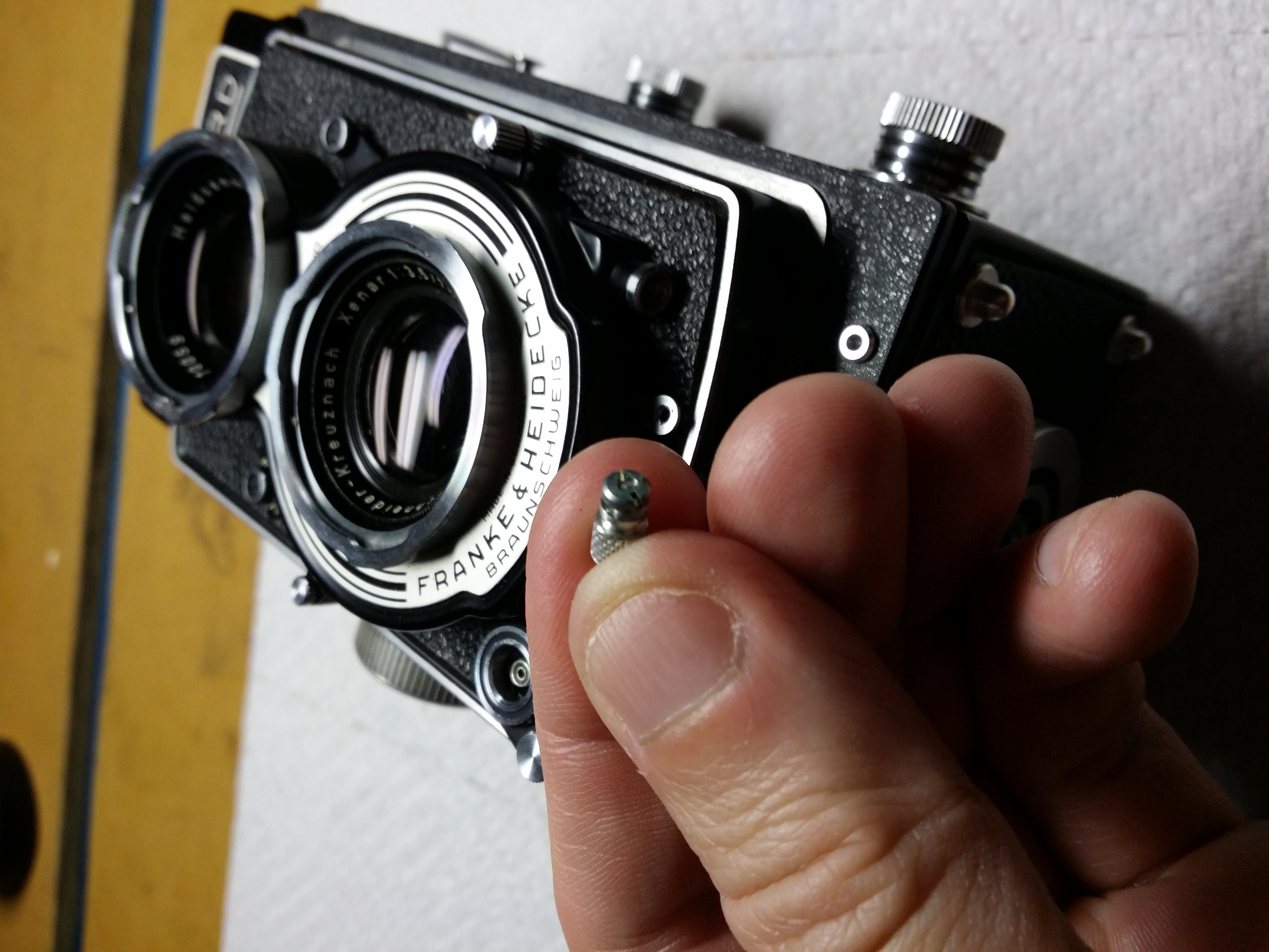
The shutter cock/trigger knob has to come off eventually, and it’s as good a place to start as any. I used a piece of heatshrink tubing to wrap it so that I could twist it with the pliers without damaging it.
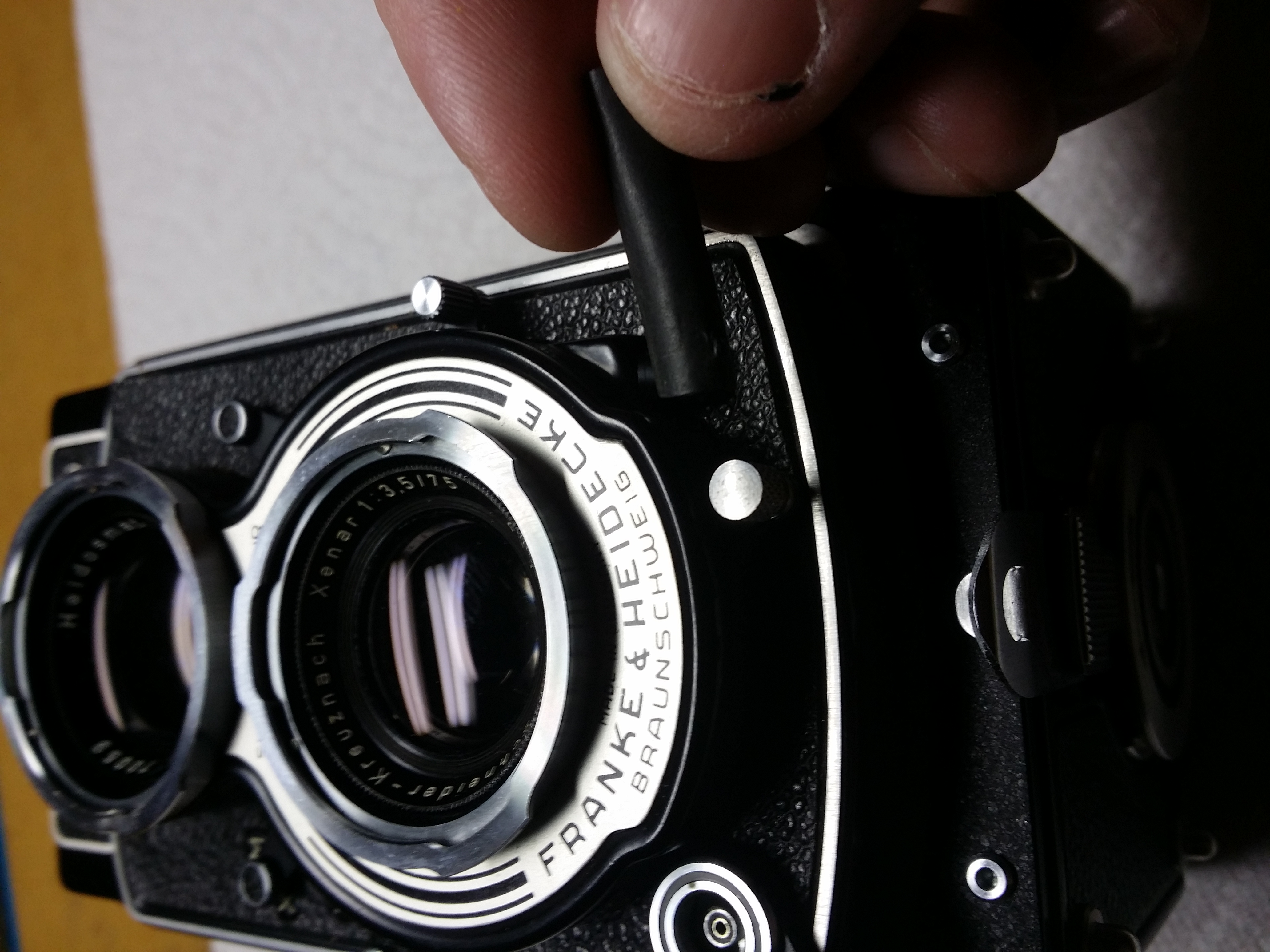
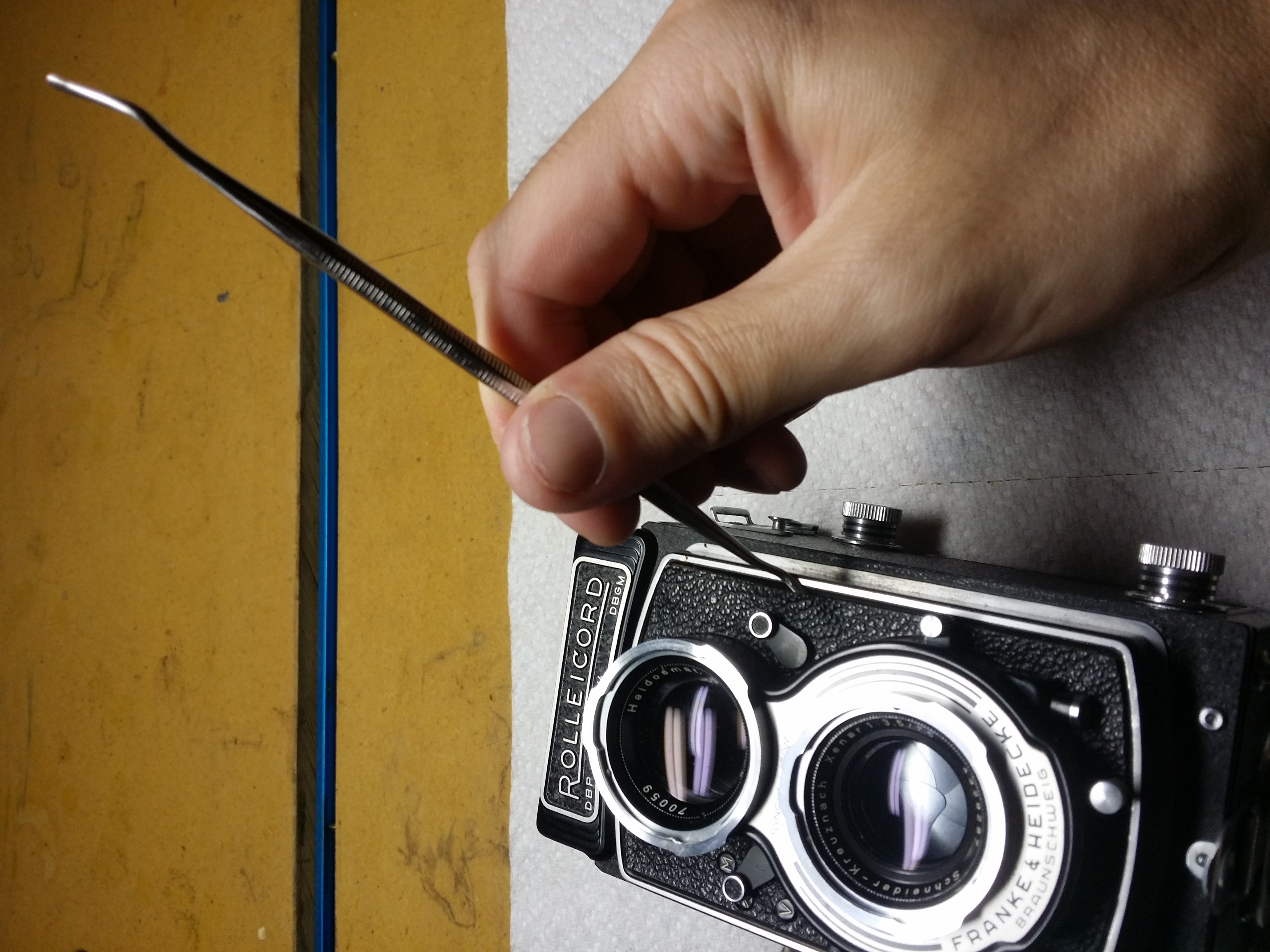
Remove the focus knob. Remove the leatherette on the front panel. Yeah, shit’s getting real. I used a dental pick, and that worked great for me.

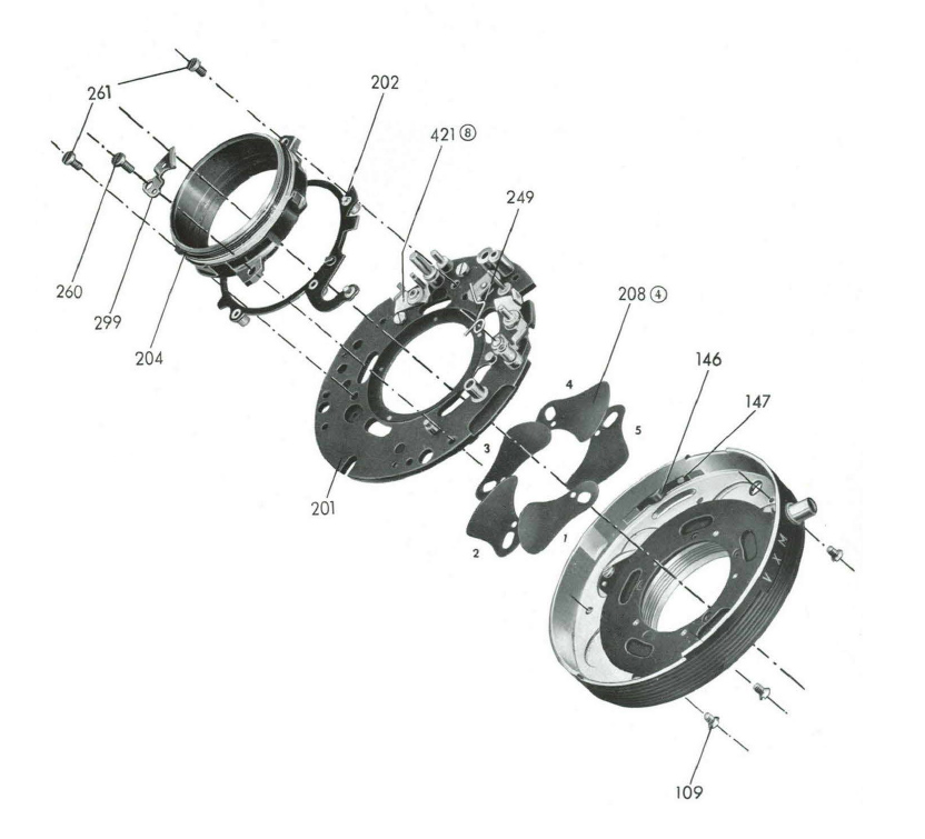
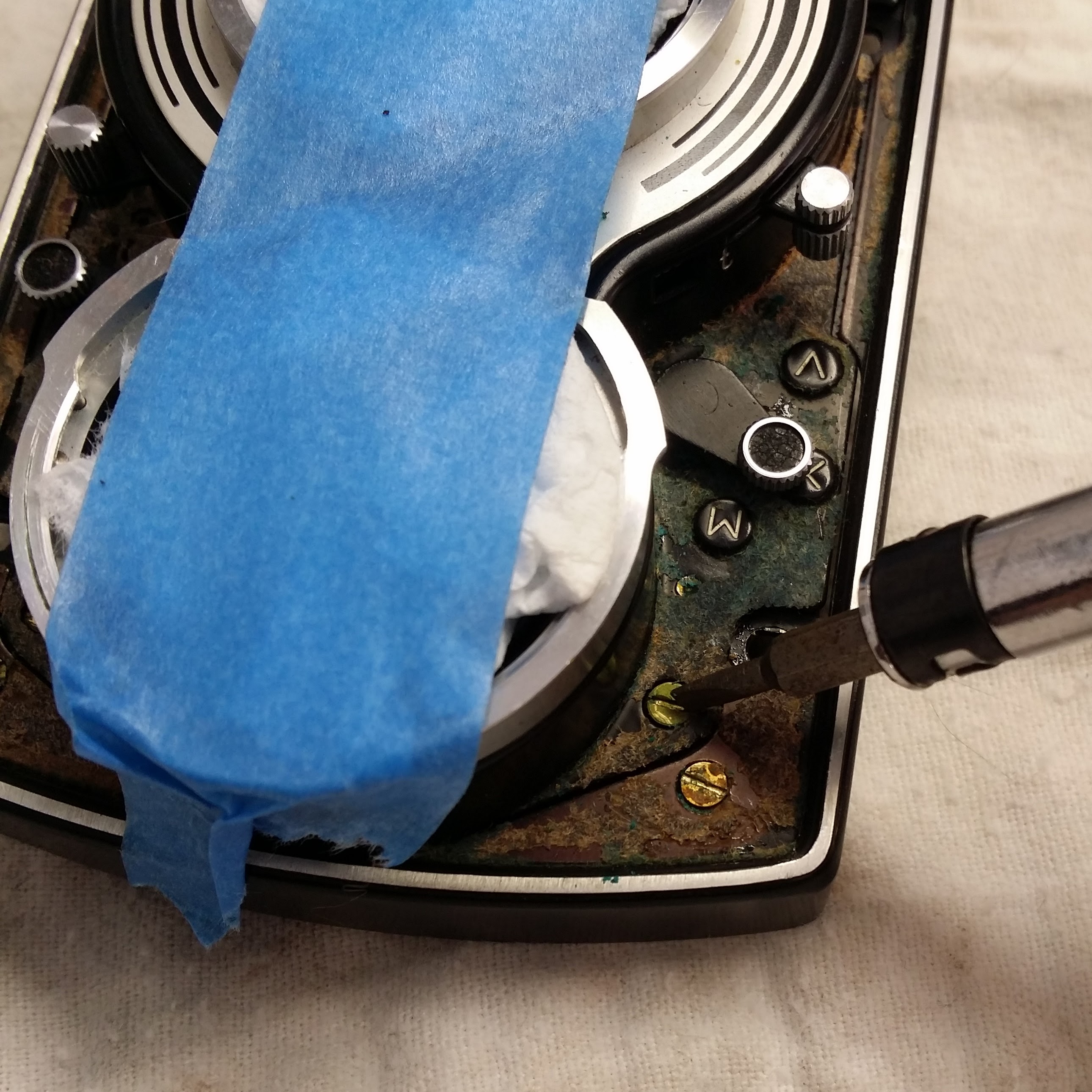
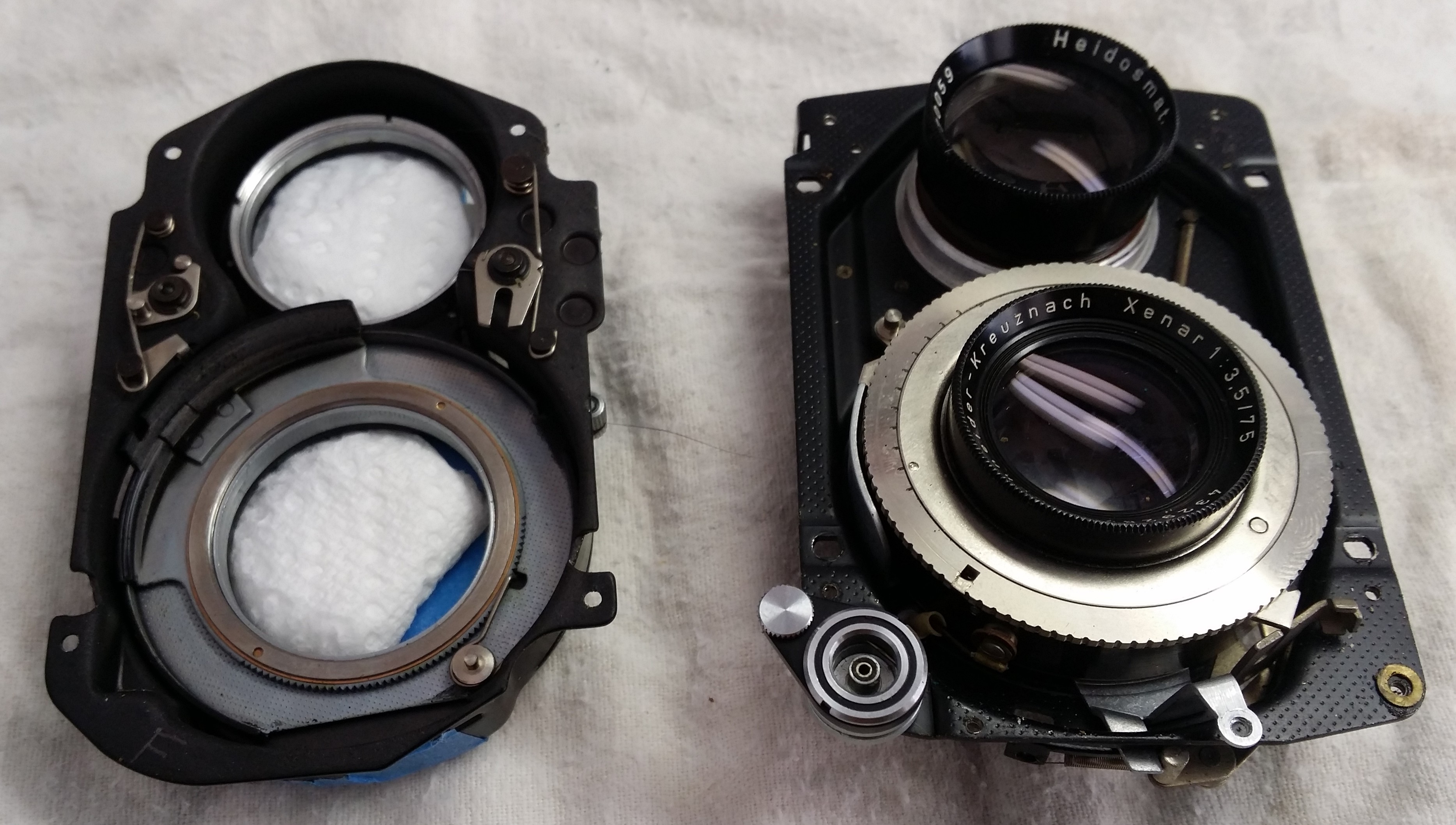
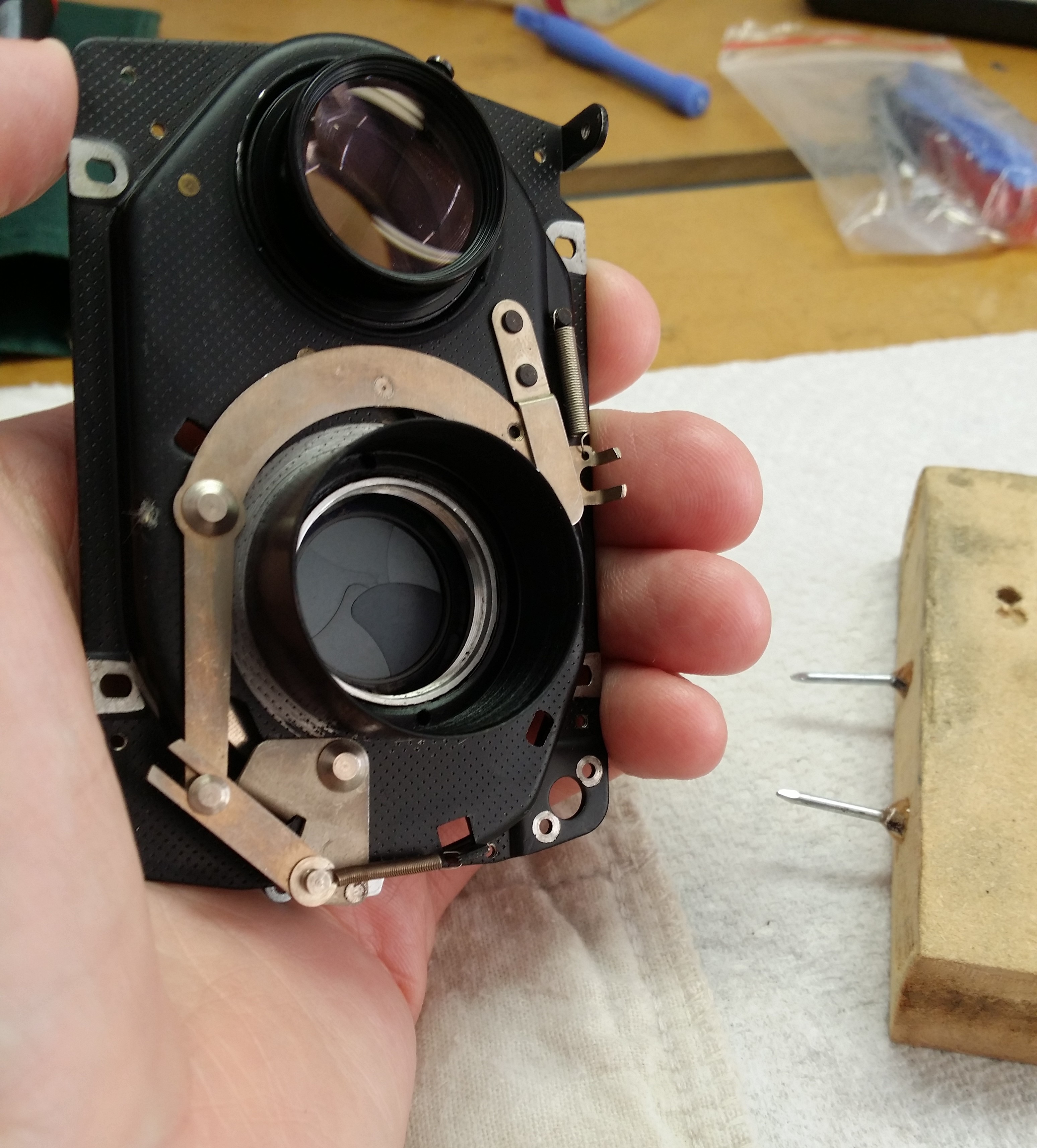
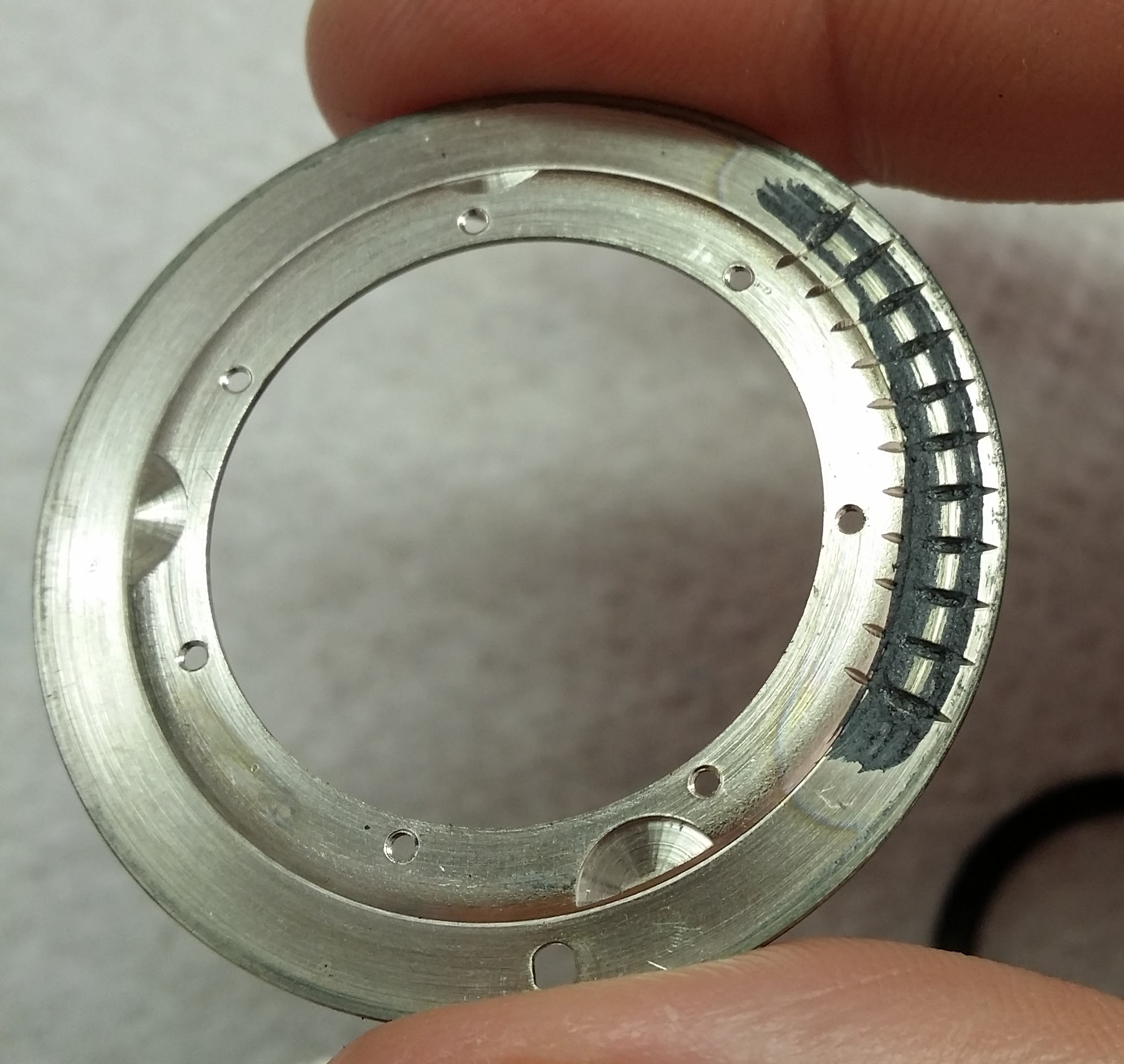
As shown in the above photo there’s three sets of screws with four in each set– an outer brass set that holds the shroud trim piece on, a larger set of steel screws that holds the lens train onto the body, and an inner brass screw set that holds the lens board onto the backing plate. You can loosen all twelve screws at once, but that is not the way of the samurai. With benefit of hindsight, I think the correct sequence is, you first do the four larger steel screws that hold the lens board onto the body. Once you’ve done those two steps, you’ll be able to lift the lens board away from the body by a quarter inch or so (with focus knob all the way out at 3′), and that gives you access to the screw in the top left that connects the lens board with the parallax correction mechanism. You can faintly see the screw in the picture below.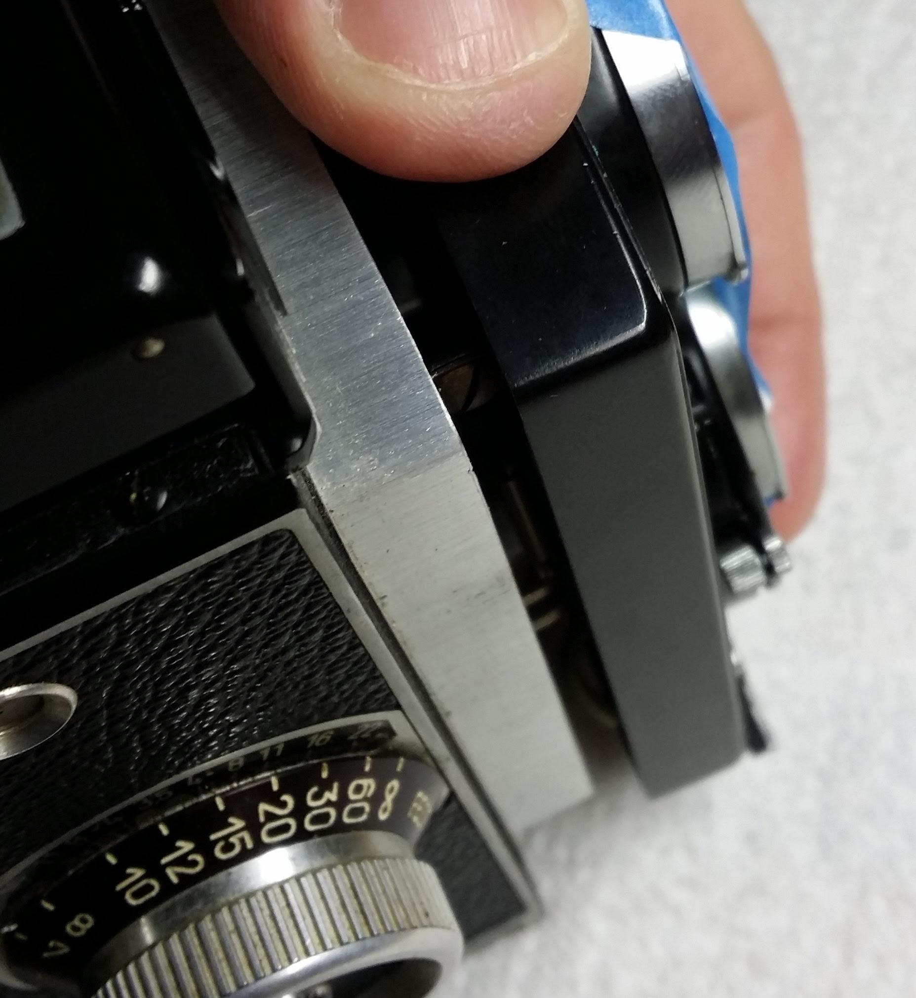 Except, don’t do it like this. Leave the camera flat on the table with the lens pointing up, because there are shims and washers underneath and if you stand the camera up they’ll fall out, and you need to document where they go. Assuming you manage not to drop any into the camera body, here’s what they’ll look like:
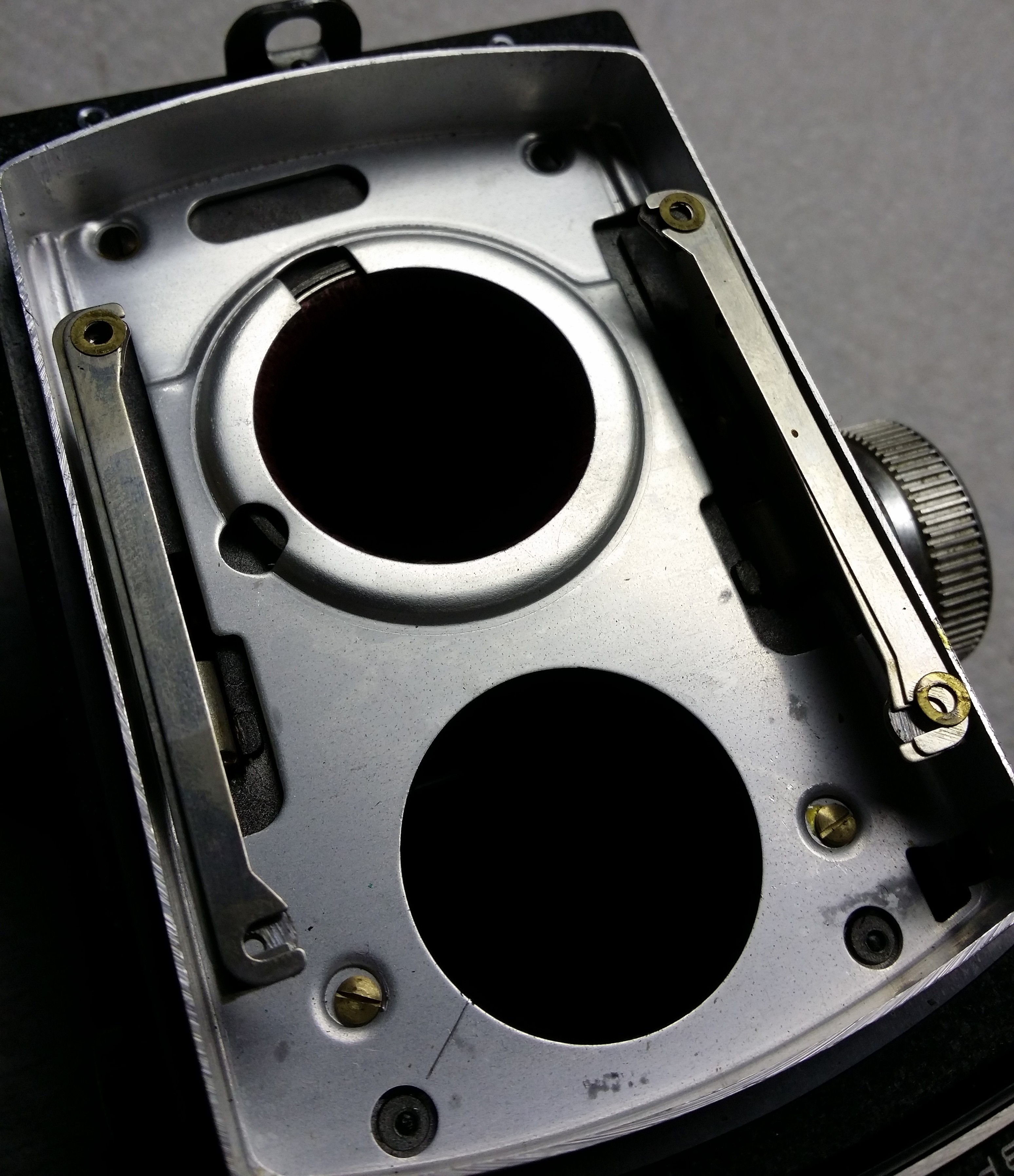
The stock arrangement is two shims per side, and one washer per hole. As I understand it, this is how you adjust focus of the taking lens, so if you’ve got more or less that might be why.
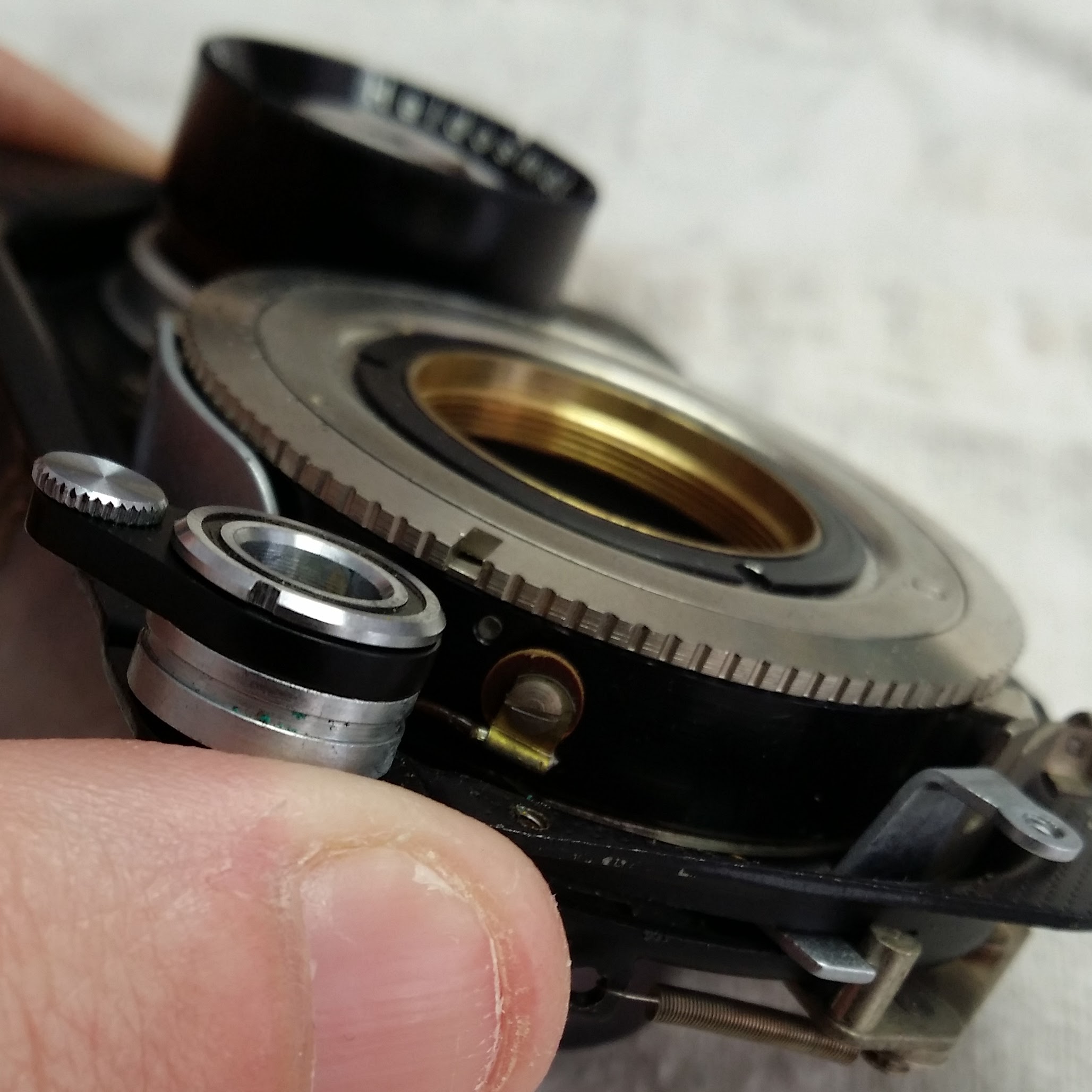
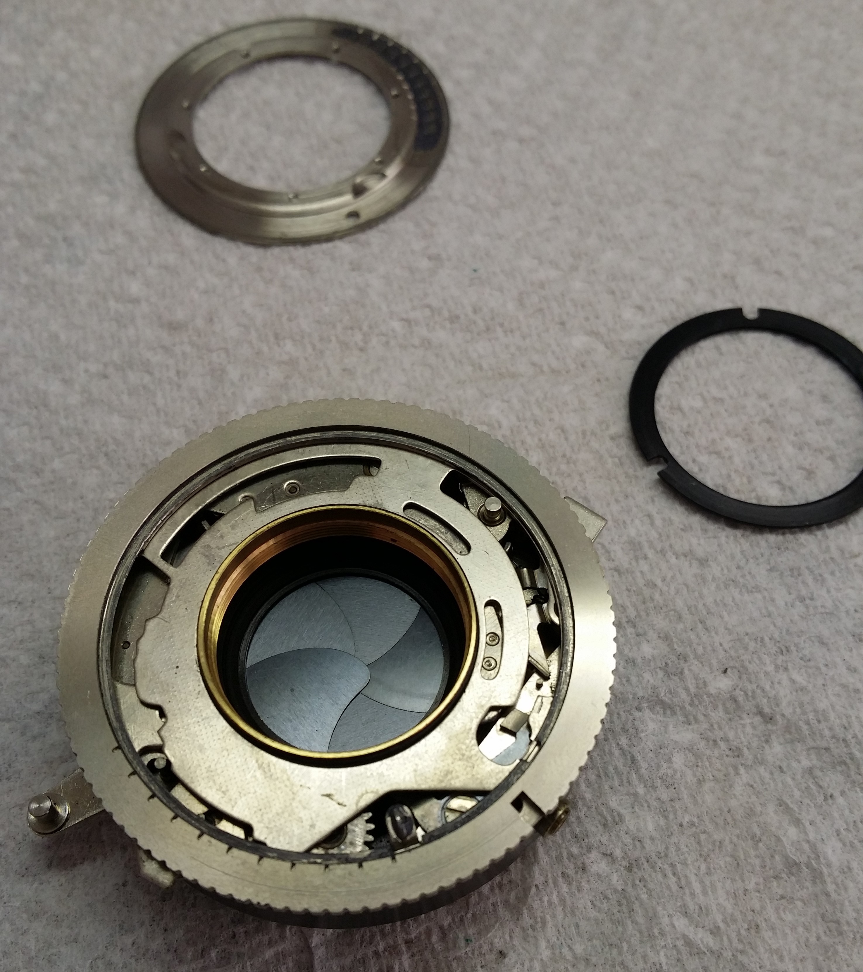
Alright, now we have the lens board off. Important point, if all you’re trying to get at is the shutter, you could probably leave the lens board on, remove the lens board cover, and loosen the rear lens shroud and lens from the back while the lens board is still attached to the camera since that’s what actually holds the shutter in place. But you’ll be working in a very narrow space within the body camera and the back of the viewing lens can get scratched if you miss, and also in my case some of the cocking mechanism exterior to the shutter needed servicing, so I elected to do it this way. Read ahead and decide which way you want to go.
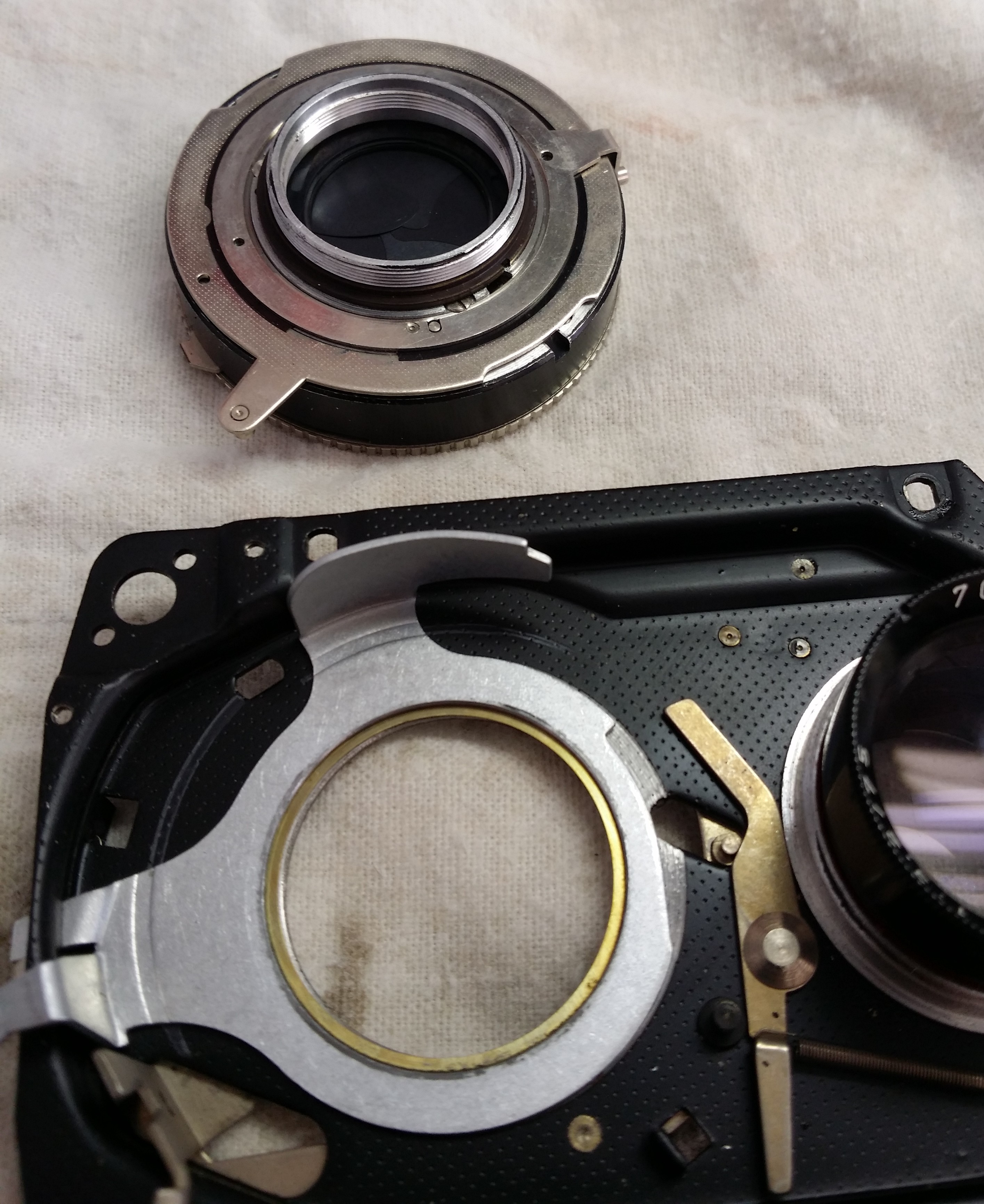
In either case, take off the four inner brass screws and remove the front cover. You’re going to have a hell of a time getting this part back on, by the way.
You’ll notice that there’s an additional washer in the lower right that was under the lens board shroud. Since I had all four of the washers under the lens board per the service manual, I was guessing that it was supposed to go under the screw that holds the parallax correction mechanism in place, and the last guy realized that he had forgotten to put it on, but didn’t want to take the whole damn thing apart again, and so stuck it under the shroud. But remember this point because during reassembly there will be a SHOCKING CONCLUSION.
You need to remove the screw that holds the flash trigger wire, and you might as well do it now. Note the resin washer. Hey, you’re putting all this stuff in labeled ziplock baggies as you pull it off, right? You can also remove the front taking lens, and I would, just to get it out of harms way. Leave the viewing lens alone.
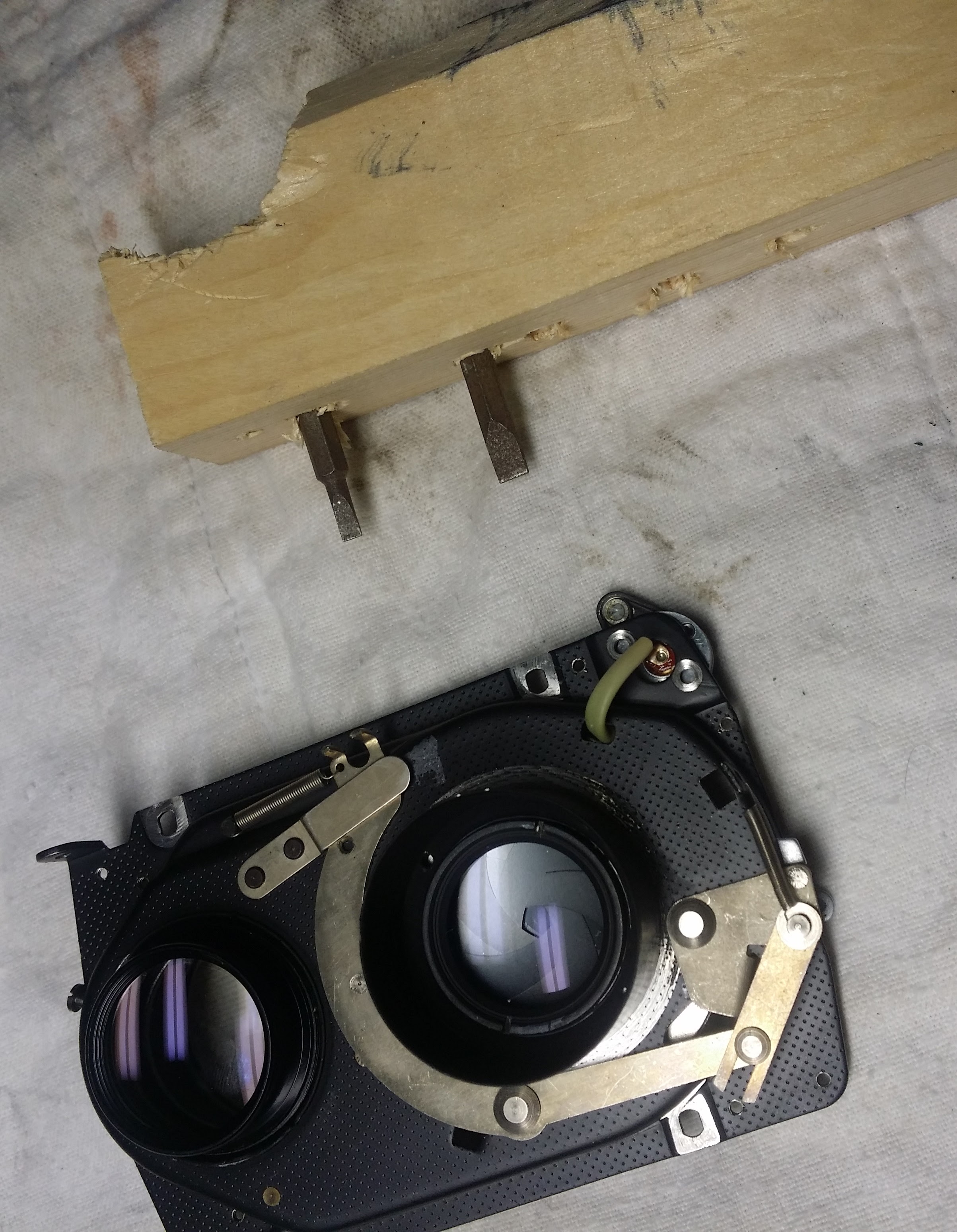
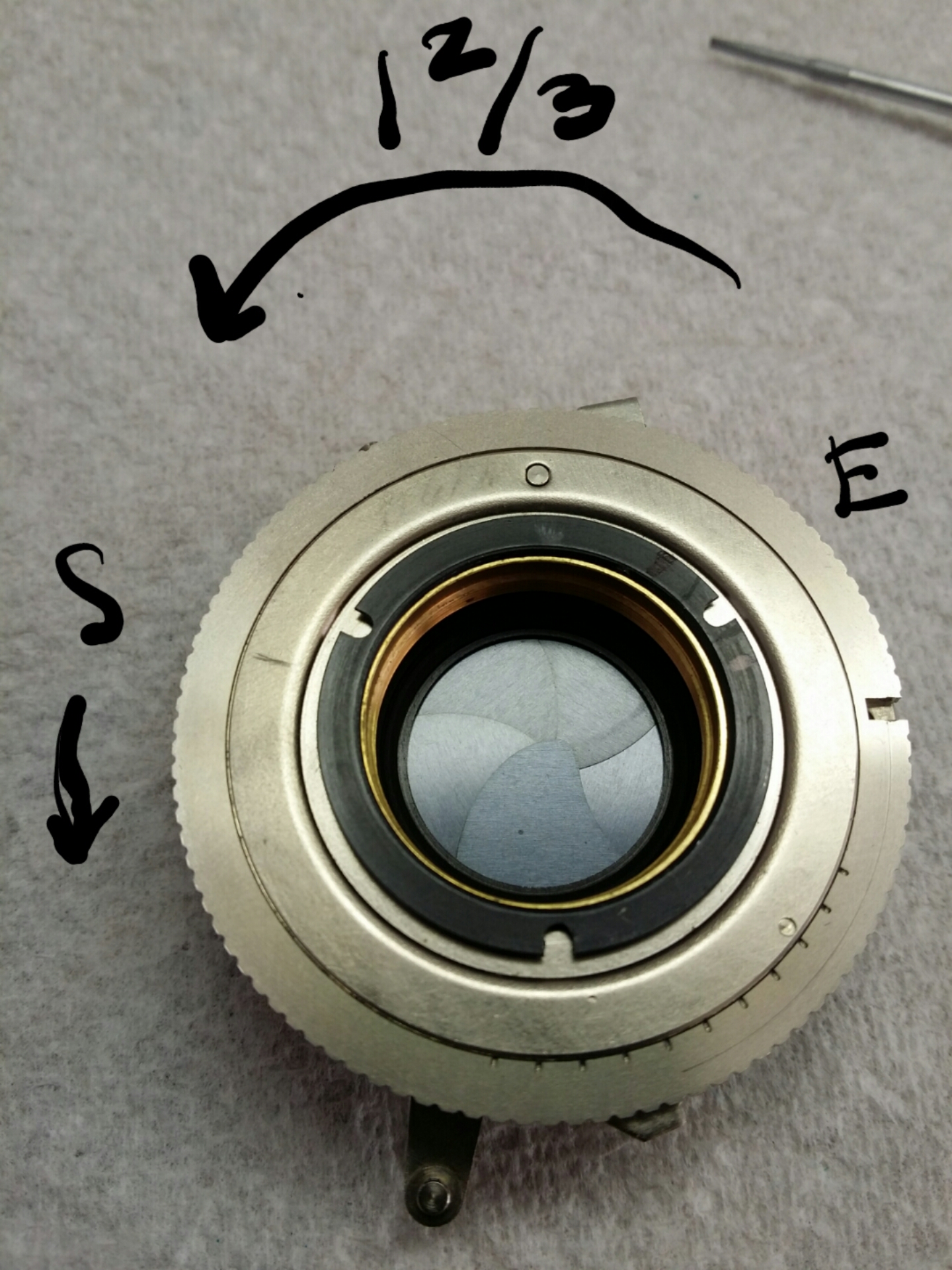
Okay, now the rear lens has to come off. You’ll need a spanner wrench for this, which will contact the slots in the back of the shroud. You can buy a lens spanner wrench for cheap and if I was going to do another one of these I probably would, but I didn’t want to wait for shipping and so I just made one out of a scrap of wood and two mini size screwdriver bits, and that worked fine for me.
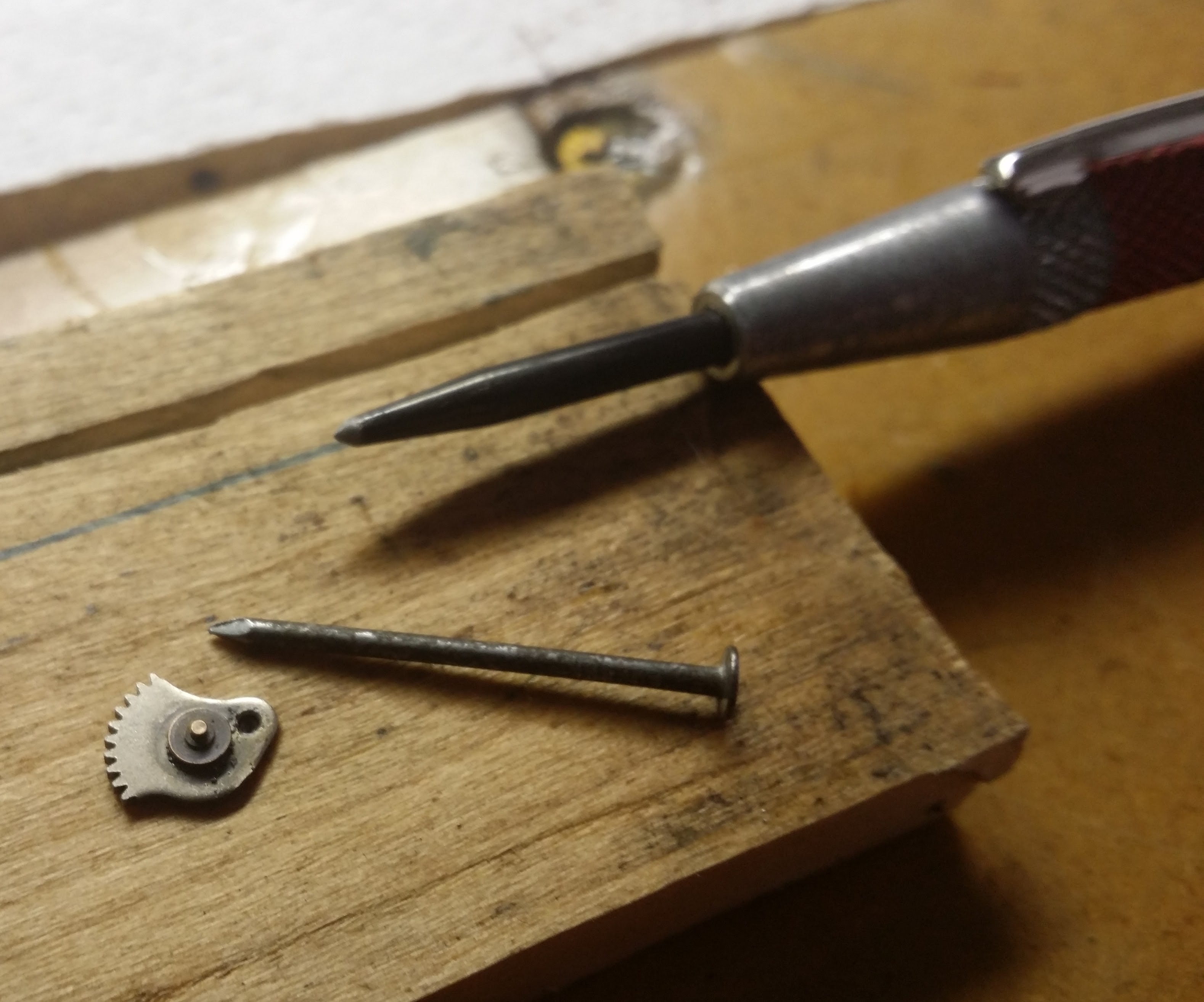
Now that the lens is removed, you’ll a need a spanner wrench with points instead of blades to remove the lens shroud. Again, I made a tool out of a pair of nails and a scrap piece of wood for this. I think a standard spanner wrench might not work, because the clearance between the holes and the inside surface of the shroud is pretty tight. Mine was completely seized, and I ended up applying a small amount of penetrating oil to the seam, being careful not to get it into the shutter mechanism, and allowing it to sit overnight. Even so, in the picture you can see it slightly bent the points of my improvised spanner wrench in the process.
You got the shutter out! Take a nap buddy, you’ve earned it.

Alright, so now we can remove the retaining ring that holds the cover on the shutter. There’s a tiny screw that holds it in place, which seems frankly unnecessary because I can’t see it coming unscrewed, but whatever. The Compur service manual just says that this ring should be adjusted for “smooth operation” and it’s probably already in the right place, so document where it was because there’s six screw holes and three possible positions on the ring.
The shutter cover indexes to a post, and can be removed by itself or you can actually lift it off with the timing ring at this point.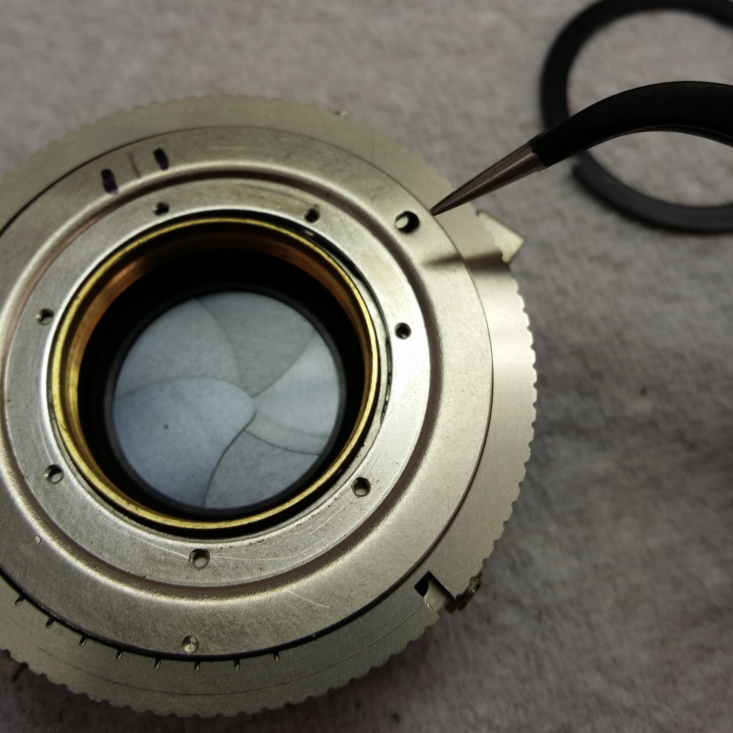
You can then remove the aperture dial, being careful not to lift anything else out with it if the insides are gummy.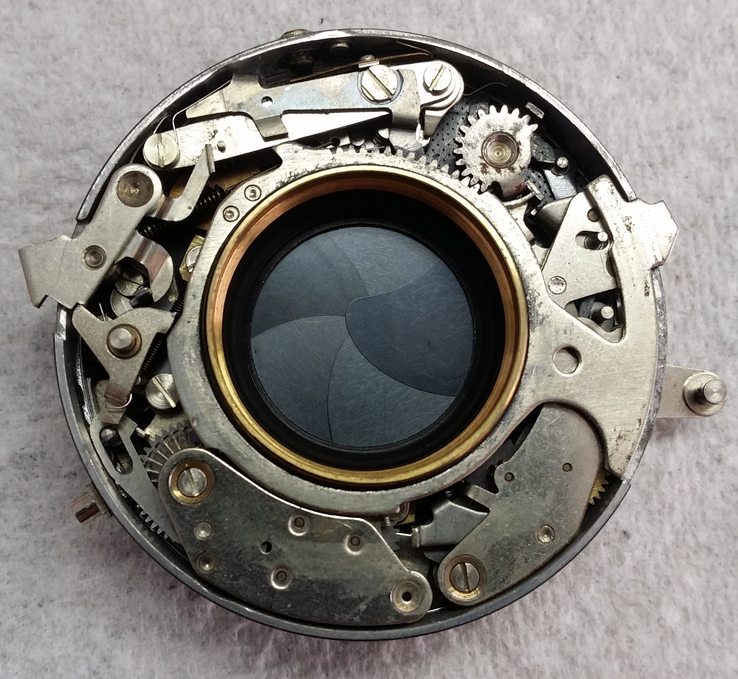
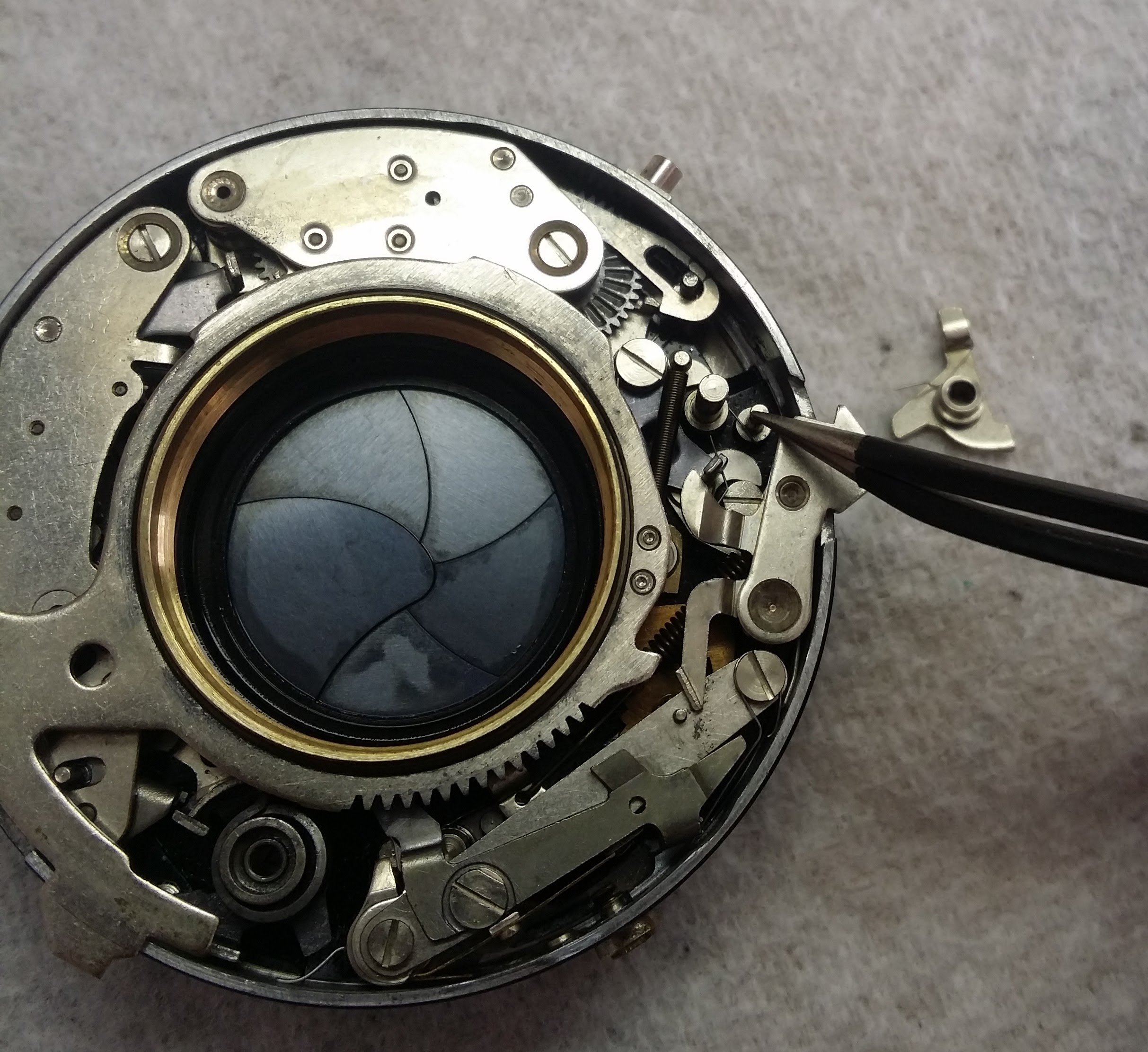
All right, let’s take stock. At six o’clock, there’s the self-timer escapement. On mine, this sounded like a dying fly buzzing against a window, so I knew that had to come out for service. Moving counterclockwise, there’s the slow gear escapement between 2 and 5 o’clock, which engages in for times 1/8 second and slower. At twelve o’clock, there’s the flash synch mechanism. At 9 o’clock, there’s the trigger release. That triangular lever isn’t held down by anything, and it has a tendency to lift up and release the spring that you can see wrapping around the bottom lobe and poking out above the top of the gear. At 2 o’clock, there’s the tensioning pinion. Finally, the ring running around the center that tooths into this gear is the cocking rack, and it has to be correctly in contact with (1) the lower step on the inner diameter (2) the stop at the outside of the case at 2 o’clock (3) the triangular gear at 9 o’clock (not actually touching though) and (4), this is the one you’re going to miss, the self timer lever at 6 o’clock. I think in the picture above it might actually not be in proper contact with this last lever, actually, it’s easy for it to slip over. Here’s a picture.
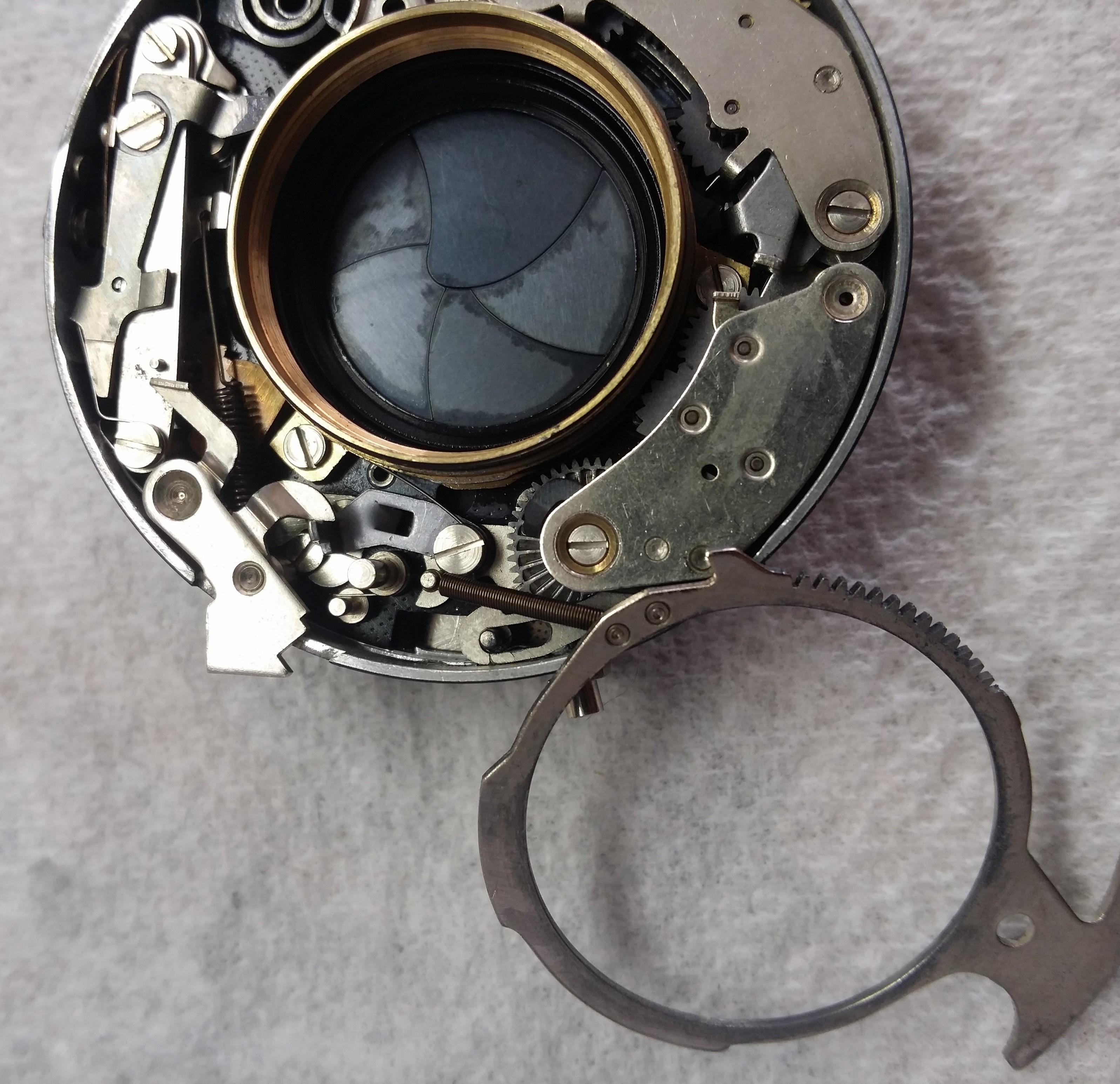
The cocking rack is also attached to a spring that you can see under the works at 10 o’clock, sooooo yeah it’s tricky to get on and off. But! You’ll get plenty of practice, because once you clean out all the gak your timings will probably need adjustment, and you have to take this ring off and on multiple times when you’re adjusting it. I found that the easiest way to get it on and off was just using my fingers, of course with latex gloves on so you don’t get your finger oils everywhere. You can and should rotate it slightly clockwise just to understand how everything fits together while holding it down, but obviously don’t try to cock or fire the shutter at this point.
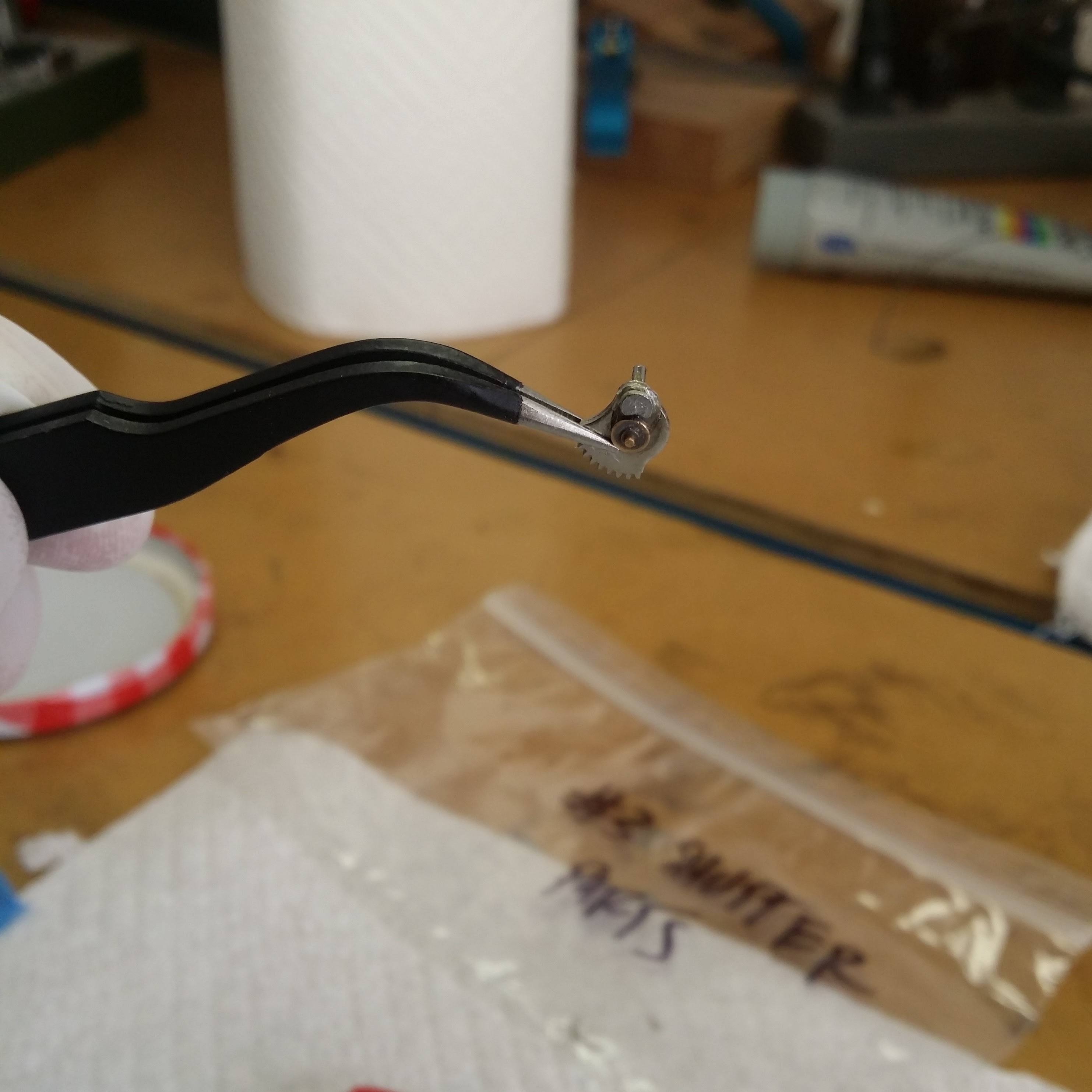
Are you ready for this? Valar morghulis. Take out the triangular lever and tensioning pinion by pulling them straight upward. They both have some spring tension on them, so they’ll snap out of position as soon as they clear the shutter release and the cocking rack, respectively. In the photo below, the tweezers are pointing at the post that the spring engages on, and next to it is the post that the triangular lever rotates around.
Now remove the cocking rack.
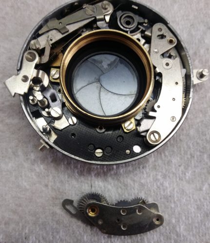
Now remove the self-timer and slow gear escapements. Since the position of the slow gear escapement relative to the case is used to set the timing of the slow gears, you may want to make a note of where it was, but the times will probably be different once you clean everything out and re-lubricate anyway.
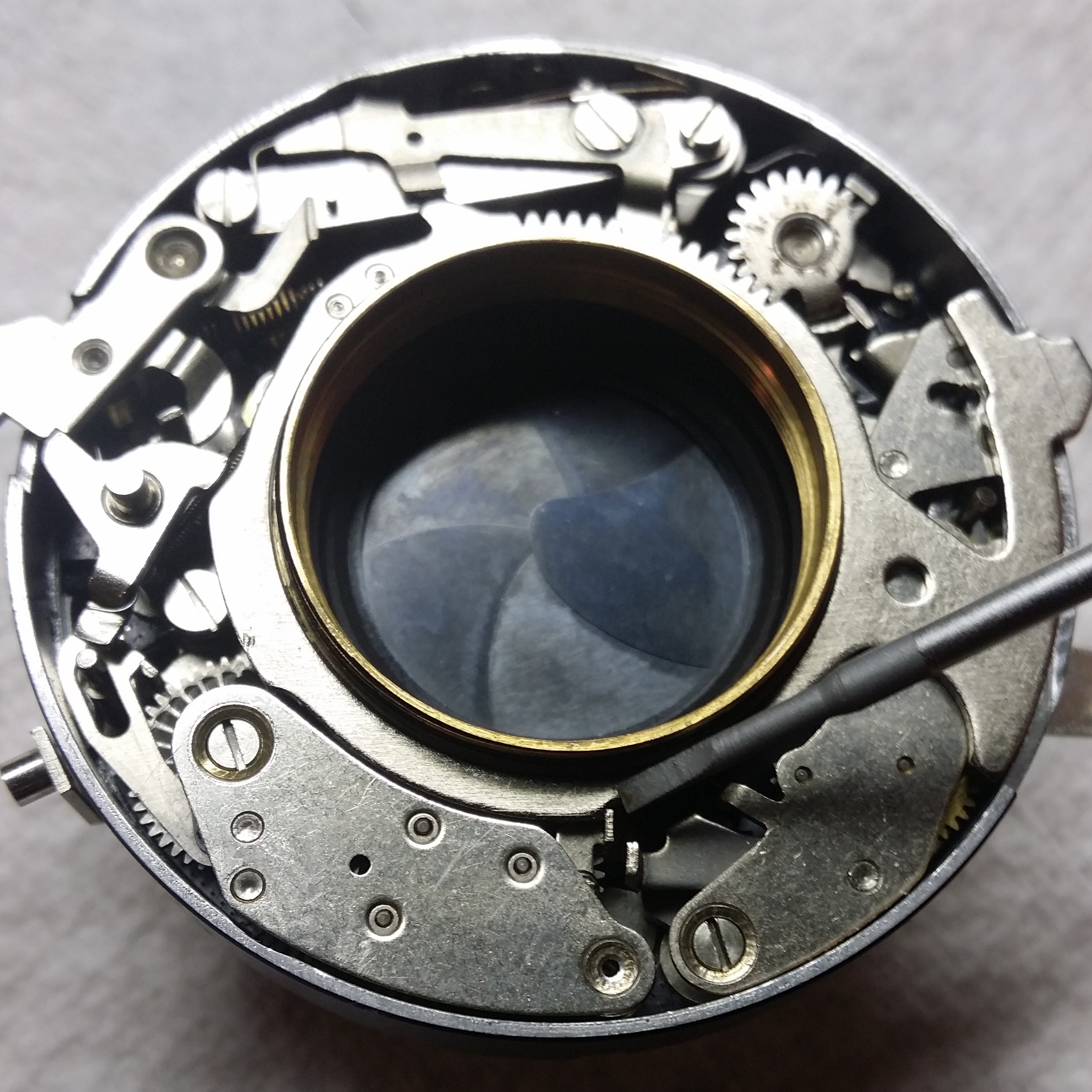
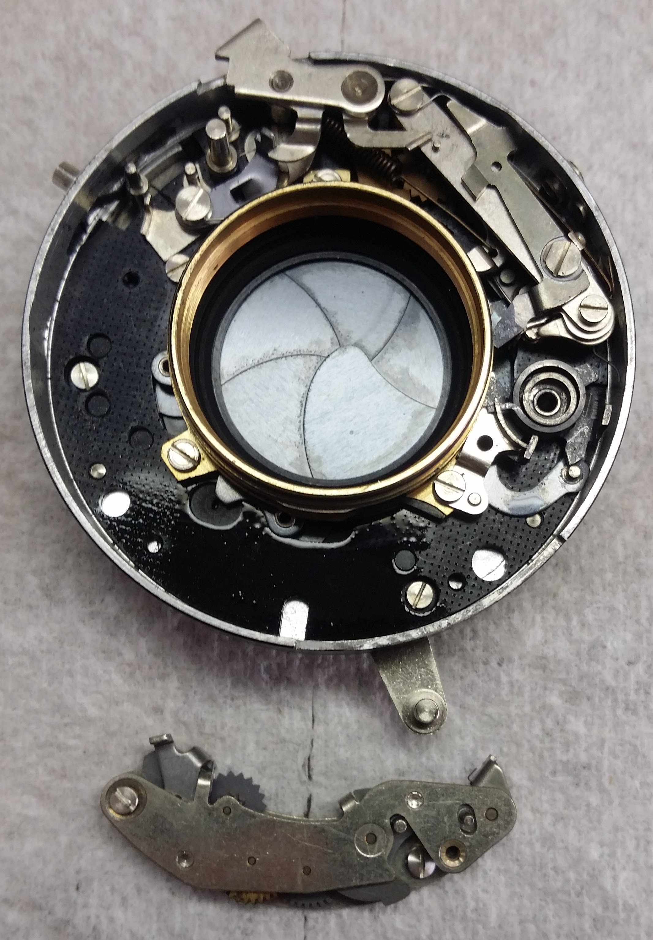 Okay! you now have unobstructed access to the shutter lever, which is at 4 o’clock in the picture above. For me, this was as far as I felt like I needed to take the disassembly to properly clean and re-lubricate it. If your shutter leaves or aperture blades have corrosion, you may need to open up that part of the mechanism and actually take them out and clean them.
Okay, so the Compur service manual recommends two solvents for cleaning: trichloroethylene or perchloroethylene. Trichloroethylene is now categorized as a known carcinogen and is not easily available. Perchloroethylene (PERC) is apparently what you’re smelling when you go to the dry cleaner, and is merely a probable carcinogen. You can order PERC on Amazon, unfortunately no Prime two-day shipping though. What both chemicals have in common is that they’re excellent degreasers that leave no residue. The readily available alternative is Naptha (lighter fluid), which is a pretty good degreaser that leaves very little residue. Also I had some of that so that’s what I used (in a well ventilated area and using gloves, because Naptha is Category 1B for mutagenicity so, surpriiise, probable carcinogen). I first let the whole mechanism soak in the solvent overnight to loosen everything up, and then I used a small paint brush with bristle fibers to clean the geared parts with more solvent. I felt like the brush gave me some good scrubbing action without the risk of bending or disengaging a spring, and since the fibers were relatively large it was easy to see if I was leaving one behind in the mechanism. For the shutter and aperture blades, I worked them back and forth while flushing them with solvent, and then used some lens cleaning cloth wrapped around a popsicle stick and soaked in solvent to dab them clean while working them until they showed no oil-slick from dissolved lubricants. Don’t use cotton swabs (Q-Tips), they leave lint behind.
This Section is about Lubrication: Okay, so now the mechanism is nice and clean, and it’s time to re-apply lubricant. There’s a lot of confusion on how and even whether to lubricate your shutter on the internet and all I can say is RTFM people, because there are clear instructions on how to do this. Well, except that the Compur manual makes reference to a “Lubricant A” and a “Lubricant C”, without any explanation of exactly what they are– you’re supposed to buy them direct from the factory. Lubricant C is easy because it occurs in just a few places where larger parts have to slide past each other, and so we want a thicker grease-type lubricant that will cushion the parts from each other and doesn’t dry out. I used Super Lube grease, which is PTFE/Teflon based and stays slippery even after it dries out.
Lubricant A is used on all the fine clockwork pieces, and the manual specifies that you’re to shake it vigorously before applying. To me, that sounds like graphite power suspended in something, but it could also be two immiscible lubricants, or perhaps a tasty vinaigrette? This guy uses molybdenum and based on his use of words like ‘pawl’ he seems to know what he’s about, but I haven’t worked a lot with powder-based lubricants and I wasn’t sure if I would be able to keep a powder off the lenses so I wanted to stick with a liquid. I used watch oil since like shutters watches contain small parts that have work with a minimum of friction over a wide variety of temperatures, without getting gummy or attracting dirt, for long periods without maintenance. Also watch oil is non-spreading. If you read camera repair forums you’ll find people advocating everything under the sun as a lubricant and insisting anything else will destroy your shutter, which means it probably doesn’t matter that much what you use. Any synthetic lubricant available today is going to be far superior to what was available in 1954.
On the matter of where to apply lubricant, there’s several pages of illustrations listing specific points, and also specifies that all bearings and brass teeth in escapements should be lubricated, plus all shafts, bearing bushes mounted to the base plate. So basically anywhere one piece of metal rubs against another, except “gear wheels and pinions having a grey lustre have been lubricated by a special process during manufacture and never need any subsequent lubrication” and “the [shutter] blades 208 and their bearings must be completely free of grease” and “diaphragm Segments 105…and their bearings should be kept completely free of grease.” So, don’t oil the shutter blades or the aperture blades, contrary to what you might read elsewhere, on the internet. As to how, the manual suggests “Apply a thin film of the prescribed lubricant to a glass plate and use a fine brush or foam rubber swab to apply the lubricant at the required points.” I used this technique with a very small paintbrush and the lid of a clean tin can and it worked great for me.
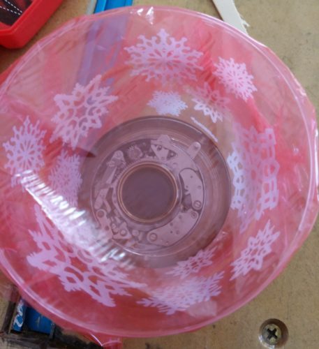
Assuming you’ve got it all lubricated and re-assembled, it’s time to adjust the timing. The way I did this was I hooked up an LED directly to my oscilloscope leads and placed it at the film plane, and then shone a bright light through the lens. LEDs and for that matter all diodes produce a small amount of voltage when light is applied to them, so you can set the oscope to single shot and measure the width of the voltage pulse when the shutter is open.

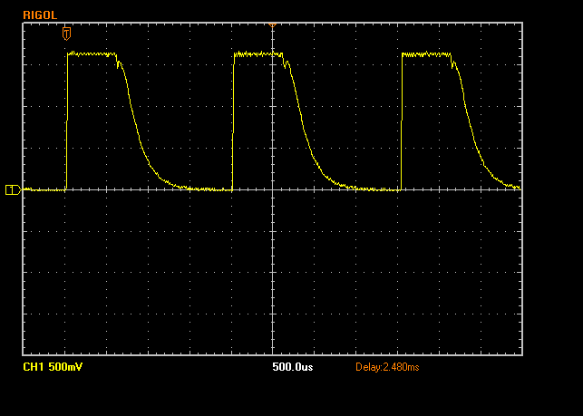
This worked great and if you can at all get your hands on an oscilloscope I would use this method. For the LED, I tried every color I had at hand and the clear winner was an amber LED with clear casing. Under strong light it would output as much as 2V. If you’re questioning whether this is really all that accurate, here’s what it looks like when I shine my LED flashlight on it– that sawtooth pattern is the buck-boost voltage converter in the flashlight kicking on and off. Note that the time scale is 500 microseconds. So, plenty accurate for our needs.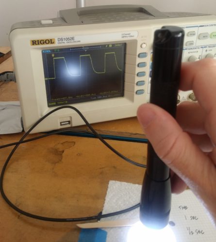
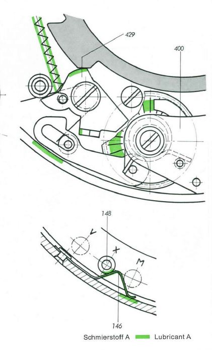
 Adjusting the timing occurs in two parts. First, to adjust the slower times (1, 1/2, 1/4, 1/8), you adjust the placement of the slow gear escapement per this diagram:
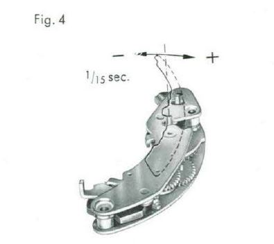
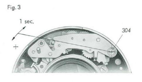 The screw on the left can be loosened and the entire assembly moved closer to the center (slower) or towards the perimeter (faster). That’ll take you a bit of fussing to get right but there’s nothing difficult about it. And… here’s where things are going to go off the rails. To adjust the faster times (1/15 to 1/250) you’re going to have to bend the fucking pin on the escapement. Yes, really.
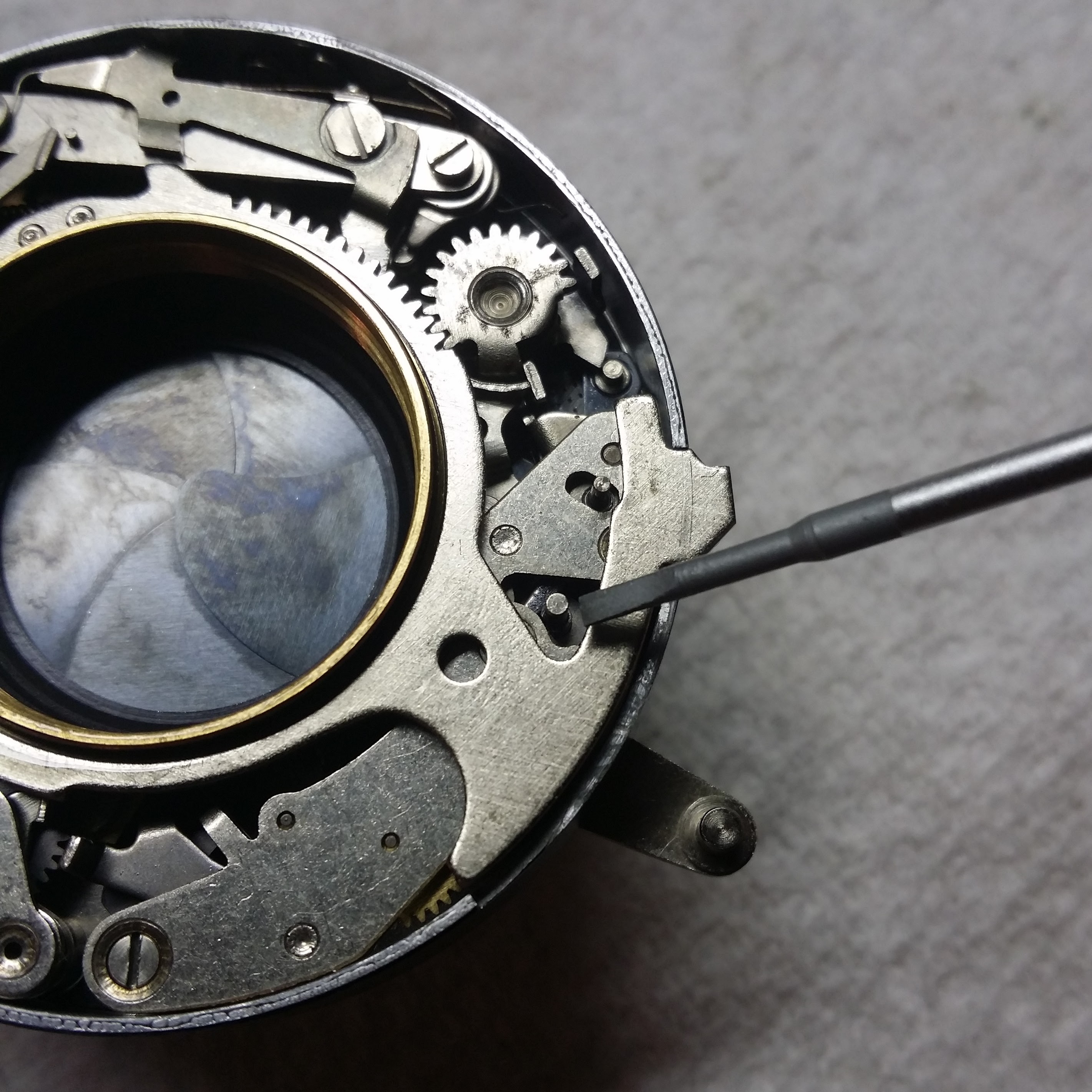
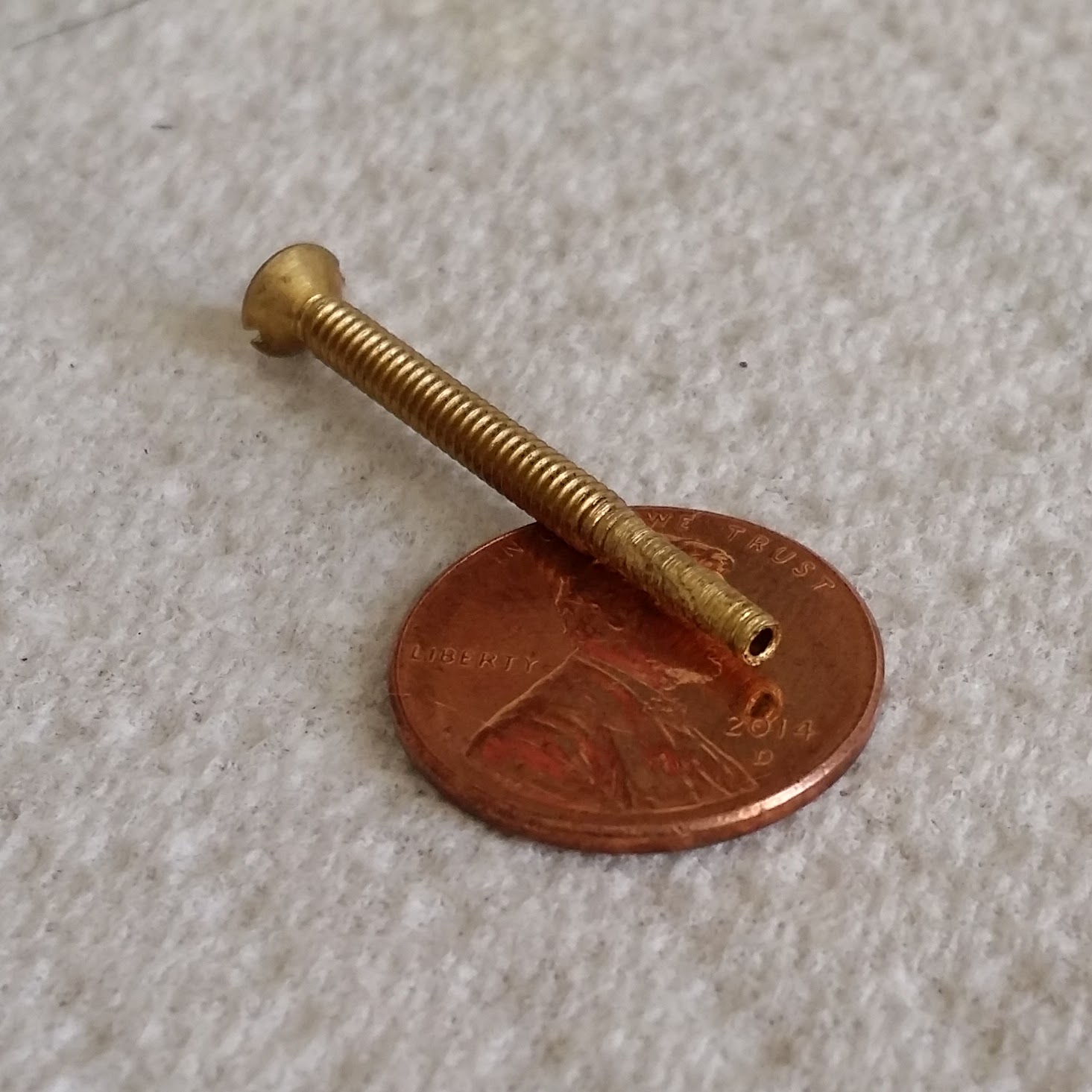
You can’t use pliers or anything like that, because (a) it’s not nearly precise enough and (b) you’ll squish the pin. I made a tool by drilling into the tip of a brass screw with a 1mm bit, then removing the extra bulk from the threads, and that allowed me to apply a very precise and repeatable amount of torque:
The other thing is, the timing subtly interact with each other– changing the 1/15 time will change your slower times, and vice versa. So, if you have the option of leaving this alone, I would exercise that option. It’s going to take you a few tries to figure out the right amount of force (you won’t be able to see the pin move, it’s all by feel), and by that time you’ve put a fair amount of fatigue into the metal, and that pin is only 1mm in diameter. And in fact, just as I was getting a feel for it… I broke the pin. Snapped it right the fuck off.
I figured at this point I was going to have to buy a junk shutter on ebay and cannibalize it, but before I did that I figured there was no harm in trying to fabricate a new pin. I managed to drill out the rivet holding the old pin, by drilling away most of the rivet head and punching the rest through with a nail and this ratchet awl thing I’ve got:
Tangent about this tool, it has a spring ratchet mechanism so that you push it down until the hammer fires, at which point it punches into whatever it’s held against. It’s turned out to be super handy both for the intended purpose of creating divots so that your drill bits don’t walk, and also any time you need to apply a precise, specific blow to something– the ratchet strength is adjustable.
1mm is just about exactly 18ga, and so I bought an 18ga brad and cut it to size. My local hardware store sells them individually, so this entire repair cost me $0.03. I also cut out the head on one side so that it would nest against the spindle, which helped with the strength of the joint:
You can actually buy precision machined miniature rivets, and if I was going to do it again I would do this because the brads were actually 1.07mm or so and so I had to drill out the hole slightly, but to be perfectly frank with you Dear Reader, I didn’t think it was going to actually work. I re-assembled the escapement, cleaned it and lubricated it again, and put it back in the shutter. After adjustment, here are my final timings:
[table id=23 /]
I’ve since shot a few dozen rolls through the camera and the timing seems accurate and consistent.
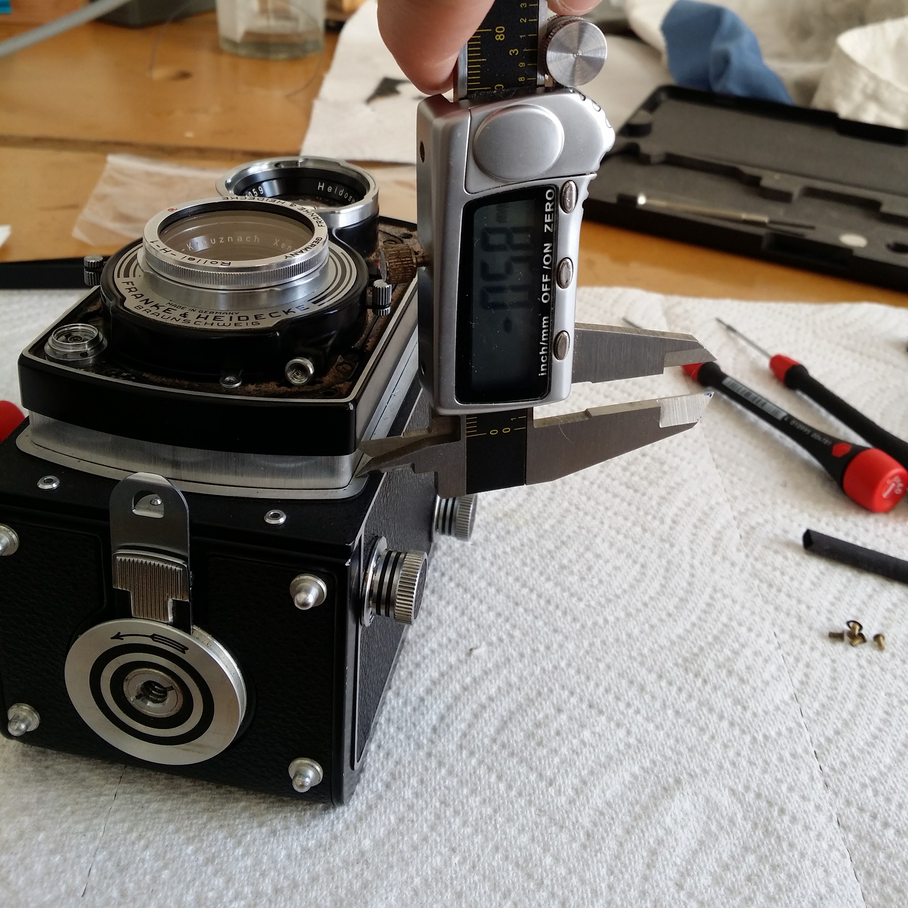
Reassembly is the Reverse of Disassembly haha J/K: So hopefully you documented everything so that it all goes back together again the way it came apart. In my case, when I reassembled everything the shroud would contact the chassis when the focus was all the way at infinity. So that’s why there was an extra washer under the lens board shroud, way back at the beginning. I measured that one corner of the lens board is .58mm closer than the opposite corner. This would be consistent with the camera taking a fall at some point and landing on that corner, which is a common issue for TLR cameras generally.
The funny thing is I can’t see any misalignment in the focus plane, either in the film that I’ve shot or by looking at the focusing glass under magnification. So I decided to leave well enough alone for now, the end.
Update: I’ve now taken this camera on a month-long road trip through Italy and France and it performed flawlessly. I’m scanning the film now, will post whenever I finish.
Great write up. How did the shots turn out? I’m rebuilding mine right now and am concerned with realignment on everything. Did you get any fuzzy corners or anything?
Cheers,
Evan
Thanks for sharing your experience. I need to CLA my rolleicord too…
This write up makes so much more sense after you have attempted to enact a Rollei repair. Fantastic job It is a shame that good, clean taking lenses are so hard to come by these days.
Having done some watch repair in the past, and buying some lenses for 4×5 and MF, there came a time of cleaning and oiling a couple of shutters.
Working on a regular old MF compur shutter (because they’re pretty similar), aside from the top “300” speed, the rest could be brought to excellent accuracy.
I finished up adjusting it so that the main speeds were as close as possible, before amending 2 speeds on the selector/ rotary cam – in the slot which the pin rides in.
It’s not practical to add material to have the correct escapement engagement (drag), but it is possible to remove a small amount of material – which depending whether the speed is slow or fast can be a solution to fine tune an individual speed – to allow the pin and escapement to engage a tiny bit more – a jewellers file can be used in the location for the offending speed.
I hope what I’ve typed here is correct/ readable – typing and retyping bits using my phone.
Anyway, it was fun and insightful to read about the rollei servicing.
Thanks very much for sharing your great instruction to re-new this old shutter.
Thank you so much for this write up! It’s a very good read and even a better practical and mental support! I am currently working on my Rollycord Va with exactly the same problems (slower shutter times and dying fly self timer). In my case there were no washers between the focus adjustment and the lensboard. Just 2 shims on each side. I only found 1 washer but at this point I haven’t figgured out where this is supposed to go. I guess it might be similar to your extra-washer-experience. In my oppinion there is way to much noise about the lubricants. Most good quality lubricats of today might work. You just need to understand the application. Is it high friction at a low speed (Lubricant 1) or is it low friction at a higher speed (Lubricant 2).
Thanks for this sassy write up :) Still working & failing on a Contaflex I, but reading this gives me hope!
As a mechanical engineer who dabbles in electrical…today I learnt that LEDs can be used as light *sensors*. Now, I have an excuse to buy an oscilloscope!